Service, Troubleshooting, Protection circuitry – Soundstream Technologies 414s User Manual
Page 14: Specifications
l
TROUBLESHOOTING
PROBLEM
CAUSE
No sound and power LED
lit
No power or ground at amp
No remote turn-on signal
Blown fuse near battery
No sound, power LED lit, and
the
option has not
been added.
No signal input
Fault LED is lit
The
switch is in the “IN”
position, Move it to the “OUT” position
Amp power supply fuse is blown or missing
Repeatedly blown amp fuse,
frequent activation of Smart
Power Supply Circuit
Speaker or leads may be shorted
Verify adequate amplifier ventilation
Channels
or 4
intermittent output
only)
activation of the internal circuit breakers.
check to make sure channels l-4 are driving
a
ohm per channel load or greater
speaker or leads may be shorted
Unable to adjust the subwoofer
midrange level separately.
only)
l
Make sure that the subwoofers are wired to
channels 1 2
No output from channels 3 4
l
Select
from ch’s 1 on ch 3 4
with 1 pair of RCA inputs
input on the bottom of the amplifier. (see
only)
pages 14 17)
Not enough input sensitivity
while using the Balanced input
only)
Left and Right Input Overload
indicators lighting
only)
l
Be sure both Left and Right Input Signal
Switches are set to the
position
l
Input signal level is too high readjust input
gains, or select the
input signal level
range
Alternator whine while using
Unbalanced RCA inputs
only)
l
Make sure the channel 2 Input Signal
Switch is in the
position.
l
Try the Input Signal Switch for channels 3
4 in the
position; leave the
switches in the quietest position. This will
not affect the performance of the amplifier.
SERVICE
Your Soundstream REFERENCE amplifier is protected by a limited warranty
Please read the enclosed warranty card.
PROTECTION CIRCUITRY
Your REFERENCE amplifier is protected against both overheating and short
circuits by means of the following circuits:
l
Main power supply fuses
l
Auto High
power supply
l
Circuit Breaker on each channel
only)
l
Smart Power Supply Thermal
activating at 85°C
l
A fail-safe thermal protection circuit activating at 95°C
Your amplifier also incorporates an innovative Fault Diagnosis System that
identifies a blown power supply fuse.
you experience blown main power supply fuses, it is likely that the
amplifier is seeing a dead short, either in the speaker wire or in the speaker
itself Rectify the problem before blowing mu/tip/e fuses! DO NOT increase
values beyond the original fuse value! Doing so will void your warranty and may
damage your amplifier.
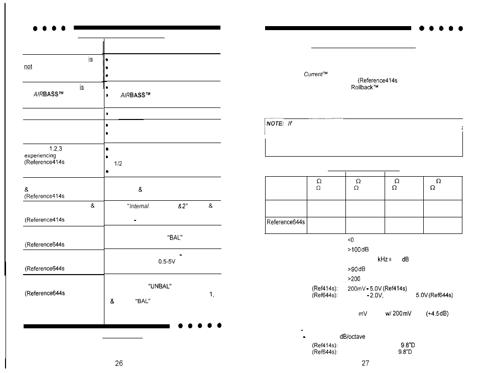
SPECIFICATIONS
POWER
(Watts)
4 Stereo
2 Stereo
1 Stereo
1 I2 Stereo
(8 Bridged) (4 Bridged) (2 Bridged) (1 Bridged)
at 12 VDC
Reference41 4s
50 x 4
75 x 4
1 0 0 x 4
NA
(100 x 2)
(150 x 2)
(200 x 2)
75 x 4
1 5 0 x 4
160x4
1 6 0 x 4
(150 x 2)
(300 x 2)
(320 x 2)
(320 x 2)
THD
1%
Signal-to-Noise
Frequency Response
20 Hz to 20
0.5
Stereo Separation
Damping
Input Sensitivity
200mV
or 500mV to
Input Impedance
1 OK ohms
Crossover Output
340
output
input
Crossover Specifications
Low Pass: 30 120 Hz at 24 dB/octave
High Pass: 60 240 Hz at 12
Dimensions
15.25” W x 2.25” H x
16.5” W x 2.25” H x