Front control panel pin definitions – SUPER MICRO Computer SUPERO X8SIA-F User Manual
Page 50
2-24
X8SIA/X8SIA-F User's Manual
Front Control Panel Pin Definitions
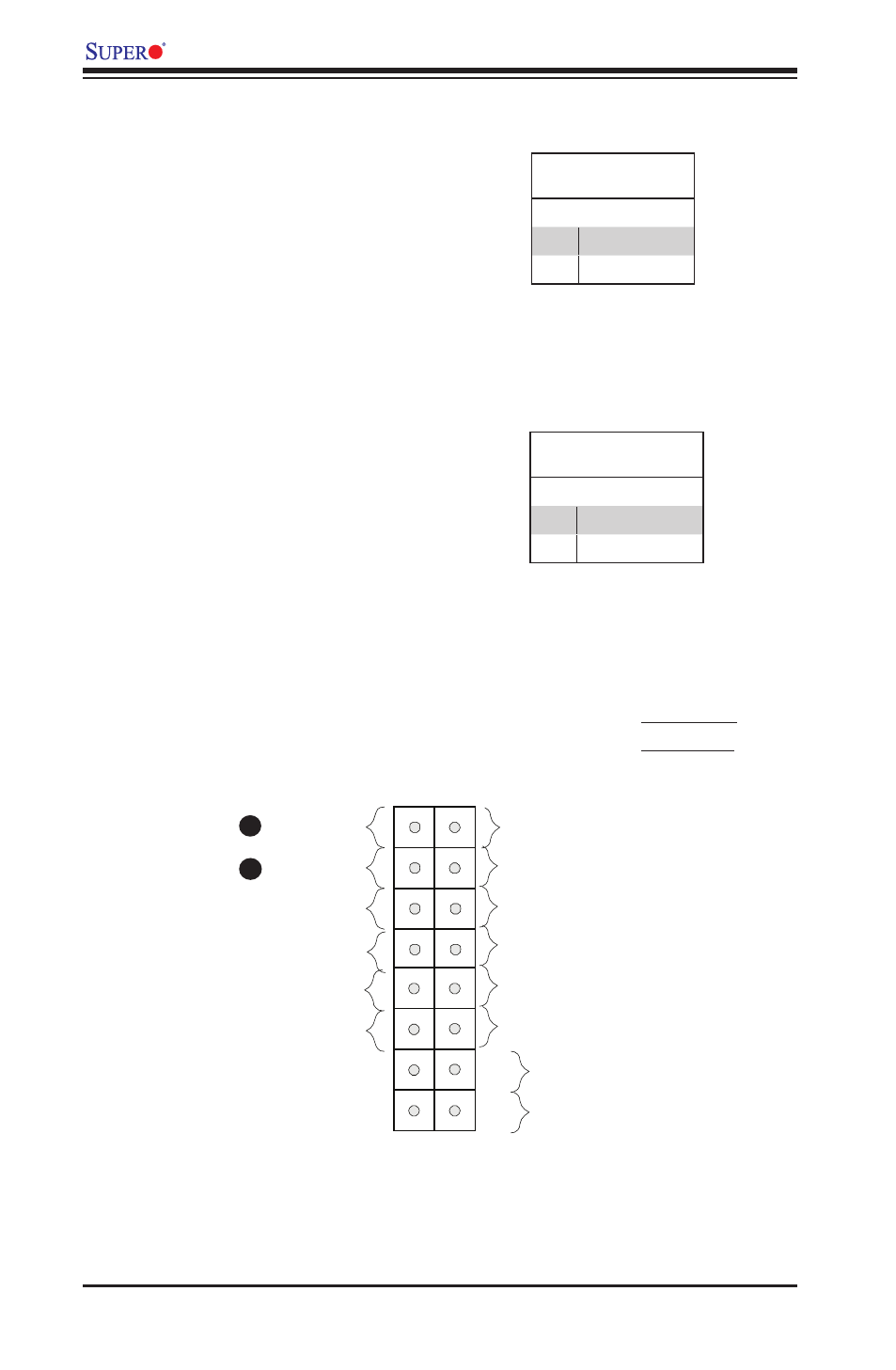
Power LED
The Power LED connection is located
on pins 15 and 16 of JF1. Refer to the
table on the right for pin definitions.
Power LED
Pin Definitions (JF1)
Pin# Definition
15
+5V
16
Ground
A. PWR LED
B. HDD LED
A
B
Power Button
OH/Fan Fail LED
1
NIC1 LED
Reset Button
2
HDD LED
Power LED
Reset
PWR
LED_Anode+
LED_Anode+
LED_Anode+
Ground
Ground
Power Fail LED
NIC2 LED
LED_Anode+
LED_Anode+
LED_Anode+
HDD LED
The HDD LED onnections are located
on pins 13 and 14 of JF1. Attach a
cable here to indicate HDD activ-
ity. See the table on the right for pin
definitions.
HDD LED
Pin Definitions (JF1)
Pin# Definition
13
+5V
14
HD Active
This manual is related to the following products: