Cone-fire, Chapter 3, Pyrometric witness cones – Sentry Industries Sentry 2.0 User Manual
Page 8: Firing schedules
Chapter 3
Cone-Fire
Cone-Fire mode is based on
pyrometric cones. It is not designed for
heat treating, glass fusing and enameling.
For these firings, see “Ramp-Hold,”
page 12. Use Ramp-Hold to fire ceramic
pieces that require a custom firing
schedule, such as some types of stone-
ware sculpture or crystalline glaze.
Pyrometric Witness Cones
The Sentry shuts off automatically without cones. Never-
theless, every ceramic firing should include at least one wit-
ness cone (also called the shelf cone). The witness cone is
the most accurate measurement of heat work in a ceramic
firing.
If you fire the same size load and type of ware regularly,
the witness cones let you compare one firing to the next and
alert you when something is wrong. For example, if the wit-
ness cone bends less and less with each consecutive firing,
this may indicate thermocouple temperature drift.
Note: If the bending of the witness cone does not
match the Cone-Fire shut-off, you may want to ad-
just Cone Offset or Thermocouple Offset. See
pages 17 - 19. If the witness cones bend inconsis-
tently from one firing to another, see “Sentry Trou-
bleshooter,” a separate publication.
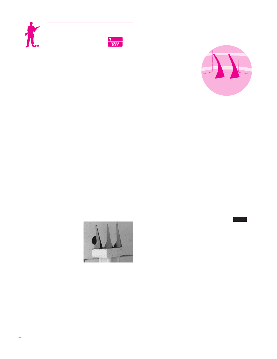
How to Position Cones on the Shelf
Position the witness cones
so that you can see them
through a peephole during fir-
ing. If the kiln takes longer than
usual to fire, you may wonder if
something has gone wrong and
the kiln is overfiring. But by
seeing the cones, you will know
how the firing is progressing.
If you follow these guide-
lines, you should be able to see
the cones even at cone 10:
■
Place the cones 8” - 12” away from a peephole. Posi-
tioning them closer makes them difficult to see.
■
Have enough space around the cones to keep them from
touching a piece of ware when they bend.
■
Position cones so that when viewed from the peephole,
they are silhouetted by an element on the opposite kiln
wall. (Keep cones at least 2” from an element.)
■
The element that silhouettes the cones should be level
with the lower part of the cone. If the element is in line
with the upper part of the cone, you won’t be able to see
the cone when it bends.
■
If you use the three
cone system, always
have the higher tem-
perature cone on the
same side in every fir-
ing. Otherwise you can
lose track of which cone
is which.
■
Wear firing safety
glasses when viewing
the cones through the
peephole.
See your dealer if in
doubt about which cone number to use with each clay and
glaze.
Firing Schedules
Cone-Fire uses three firing schedules:
■
Low fire cones 022 - 011
■
Medium fire cones 010 - 01
■
High fire cones 1 - 10
Should you ever want to customize a Cone-Fire program,
transfer the firing schedule to Ramp-Hold. See Appendix B,
pages 26 - 27.
During a cone firing, press 5 (Present Status) to see
which stage, or segment, of the firing the kiln has reached.
The number displayed will be a segment number from one
of these firing schedules.
Note: Pre-Heat shows in Present Status as
PRHT
.
It is not given a separate segment number.
Firing time in each segment is approximate and depends
on the age of elements, voltage, size of load, and the firing
speed you have chosen.
CAUTION: Cone numbers beginning with 0 are
lower in temperature than those without the 0.
When programing a Cone-Fire, be sure you know
the difference between an 05 and 5. See “Tempera-
ture Equivalents Chart for Orton Self-Supporting
Pyrometric Cones,” Appendix D, page 30.
8
Use self-supporting witness
cones on the shelf. They stand
upright without cone holders.
Silhouette the lower part of the cone
against an element. Keep the cone 8”
- 12” away from the peephole.