Example system configuration and operation flow – Sony DSR-1600.GB User Manual
Page 74
74
ClipLink Guide
Ap
pend
ix
es
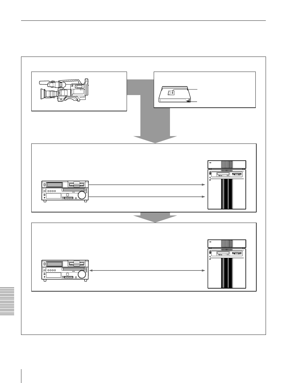
Example System Configuration and Operation Flow
The following illustration shows an example system
configuration for using the ClipLink function and a typical
ClipLink operation flow.
Shooting
DVCAM camcorder
(DSR-130/130P/
300/300P/500WS/
500WSP)
DVCAM standard cassette or DVCAM mini cassette
Index pictures: recorded on
tape
ClipLink log data: recorded in
cassette memory
ClipLink log data recorded onto DVCAM
cassettes links shooting and editing
operations.
DSR-85/1800/1600
a)
or
DSR-85P/1800P/1600P
a)
Digital Videocassette
Recorder/Player
ClipLink log data transfer
Index pictures
Video output (SDTI)
b)
RS-422A interface
ES-7 EditStation
non-
linear editing system
Editing
DSR-85
c)
/1800/1600
a)
or DSR-
85P
c)
/1800P/1600P
a)
Digital
Videocassette Recorder/Player
Actual AV data
SDTI input/output
b)
ES-7 EditStation non-
linear editing system
a) The DSR-1600/1600P is a videocassette player.
b) To transfer SDTI signals between the DSR-1800/1800P and ES-7 requires the optional DSBK-1802
SDTI (QSDI) Input/Output Board to be installed in the DSR-1800/1800P; to send an SDTI signal from
the DSR-1600/1600P to the ES-7 requires the optional DSBK-1602 SDTI (QSDI) Output Board to be
installed in the DSR-1600/1600P.
c) Between the DSR-85/85P and ES-7, quadruple transfer is possible through the SDTI interface.
ClipLink log data