Connection diagram programming – SECO-LARM USA Enforcer E-37EV User Manual
Page 5
ENFORCER E-37EV Alarm Pager System
SECO-LARM U.S.A., Inc. 5
SECO-LARM U.S.A., Inc.
33 5
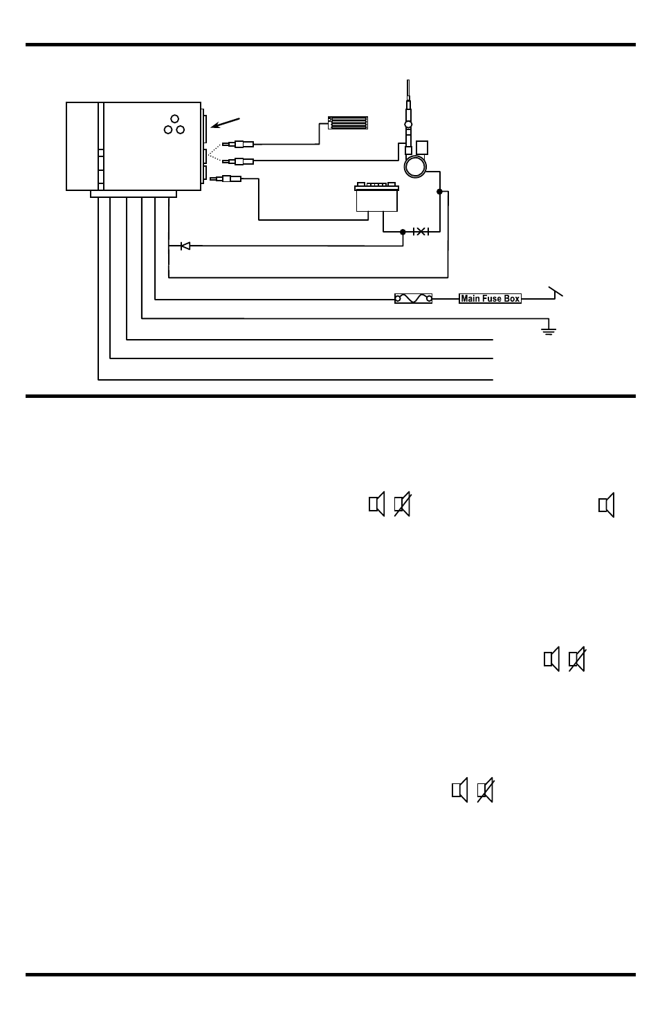
Connection Diagram
Programming
The receiver must learn the transmitter’s code before it can receive signals from the transmitter.
The receiver can learn the page codes of up to 3 transmitters.
1. Turn the receiver OFF. Then press and hold the
ON
/ /OFF switch and slide it to the
ON
position. Continue holding for 3 seconds until the receiver beeps once.
2. The PAGE LED will flash GREEN at a steady rate. The ZONE LED will be solid ORANGE.
This means the receiver is ready to learn the page code of the first transmitter.
3. Press the manual page button on the transmitter. This will send the page signal to the
receiver. The receiver will beep twice and the LEDs will turn off to indicate the code has been
learned. The receiver will beep five times in four minutes if no code is learned.
4. To learn a second (or third) transmitter, repeat step 1 then press down on the
ON
/ /OFF
switch once. The PAGE LED will begin flashing RED for the second transmitter and
ORANGE for the third transmitter.
5. Press the manual page button on the second (or third) transmitter. The receiver will beep
twice and the LEDs will turn off to indicate the page code has been learned. The receiver will
beep five times in four minutes if no code is learned.
6. If no additional transmitters need to be learned then move the
ON
/ /OFF switch back to
the OFF position.
Notes:
The receiver remembers the transmitter codes in EEPROM memory even without
power for over one year. The receiver does not need to re-learn the transmitter codes
after battery replacement.
Only one of each transmitter ID may be learned at a time. For example, if a green
transmitter is already programmed and a new green transmitter is learned, the previous
green transmitter will no longer work.
E-37ANT
(Optional)
Green:
First Negative (-) Trigger
Blue:
Second Negative (-) Trigger
Purple:
Positive (+) Trigger
Black:
Ground
Red:
Constant +12V to Fuse
Box
White (Long): Power Antenna
White (Short): Radio Switched Power
Lead
Radio (“RADIO”)
Antenna (“ANT”)
Radio
+12 VDC
Ground
Fuse (2A)
Antenna
LED
Manual Page
Antenna Selection
Switch
Cut
Diode
IN4004