Chip deflector positioning, Scale calibration – Woodstock SHOP FOX W1754S User Manual
Page 49
-35-
W1754 20" Planer With Mobile Base
SE
RV
IC
E
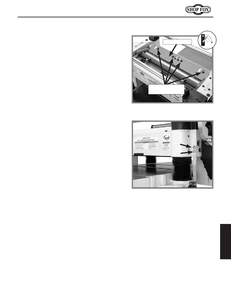
Chip Deflector Positioning
The chip deflector keeps chips from falling onto the
outfeed roller.
Chip Deflector Gap Setting ...............................
1
⁄
4
"
To adjust the deflector position, do these steps:
1. DISCONNECT THE PLANER FROM THE POWER SOURCE!
2. Put on leather gloves.
3. Remove the dust hood, top cover, and V-belt cover.
4. Loosen the chip deflector mounting bolts (see Figure
35).
5. Make sure the deflector is beveled toward the
cutterhead. Move the deflector until the edge is the
correct distance (given above) from the knife edge.
6. Rotate the cutterhead to ensure clearance by turn-
ing the cutterhead pulley.
7. Re-tighten the mounting bolts and reinstall the top
cover, dust hood, and V-belt cover on the planer.
Figure 35. Chip deflector and mounting
bolts.
Chip Deflector
Figure 36. Depth scale adjustment screws.
Scale Calibration
The scale can be adjusted for accuracy. The machine will
need to be run to calibrate the scale.
To calibrate the scale, do these steps:
1. Set the table to the approximate thickness of your
test lumber. Measure the lumber with calipers to
determine its exact thickness.
2. Move the table to
1
⁄
16
" under the thickness of your
lumber and feed your test board through the planer.
3. Turn the handwheel one full rotation and run the
board through once more. Turn the board over and
repeat.
4. Re-measure the board and compare your results
with the scale. If there is a discrepancy, loosen the
screws (see
Figure 36) and adjust as necessary.
OFF
Chip Deflector
Mounting Bolts