Alarm and status output verification – Symmetricom 58502A User Manual
Page 33
Chapter 2 Performance Tests
58502A Operational Verification
User’s Guide
2-7
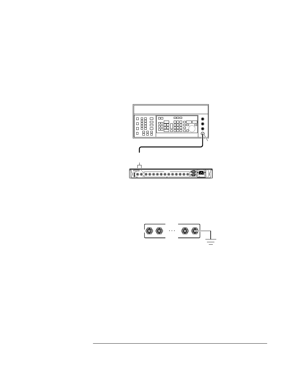
Alarm and Status Output Verification
1
Connect the equipment as shown in Figure 2-2, using output 12 as the
test output. (Note that any one of the outputs can be used for this
alarm verification.)
Figure 2-2. Alarm/Status Output Verification Setup
2
Verify the ALARM/STATUS output function by shorting to ground any
of the outputs (1-12). Let’s use output 12 as shown in Figure 2-3.
Figure 2-3. Output 12 Grounded
3
Observe that the front-panel Alarm indicator illuminates and the
ALARM/STATUS output pins (2, 3, and 4) go active (TTL low,
approximately 20 mV).
Figure 2-4 shows the output pins (2, 3, and 4) and ground pins (1, 5,
and 9.
58502A
Distribution
Amplifier
HP 8663A
Sythesized Signal Generator
or equivalent
Output
N-to-BNC
Connector
(1250-0780)
Input
A or B
A
B
1
2
3
4
5
6
7
8
9
10
11
12
5 VRMS MAX
100-240 VAC 50/60GHz
40 VA Max
!
!
!
BNC Cable
1
2
11
12
OUTPUTS