Symmetricom 58502A User Manual
Page 32
Chapter 2 Performance Tests
58502A Operational Verification
2-6
User’s Guide
3
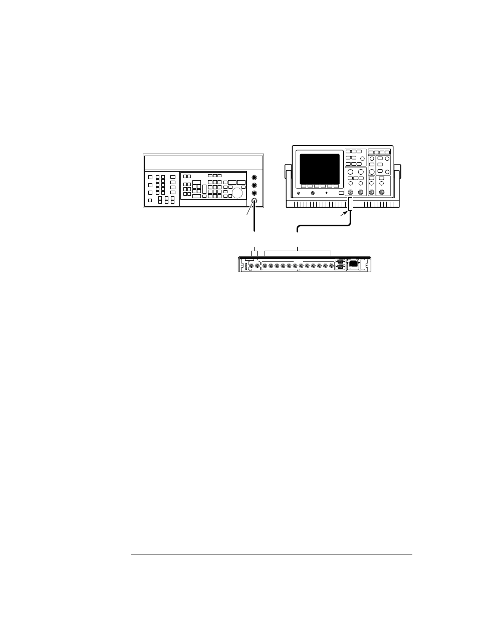
Connect the equipment as shown in Figure 2-1. (Connect the Signal
Generator output to the 58502A’s input A or B rear-panel input, and
connect oscilloscope Channel 1 to output 1 port of the 58502A.
Figure 2-1. Operational Verification Setup
4
Verify that the front-panel Input A or B and all twelve OUTPUT
STATUS (1-12) output LEDs are illuminated.
5
Set the oscilloscope to the following:
Channel 1: 0.5 V/div
Timebase: 50 ns/div
6
Connect the oscilloscope to each of the rear-panel output ports in turn
to verify that the output signal is a nominal 1 V rms (2.8 Vp-p) sine
wave at 10 MHz.
7
Disconnect the signal from the 58502A rear-panel input connector.
8
Verify that all input and output LEDs are off.
This indicates loss of input and output.
9
Mark Pass or Fail in Line 1 on the Operational Verification portion of
the 58502A Performance Test Record, located on page 2-14.
HP 54600B
Oscilloscope
or equivalent
58502A
Distribution
Amplifier
50
Ω Feedthrough
(HP 10100C)
BNC Cable
BNC
Cable
HP 8663A
Synthesized Signal Generator
or equivalent
Output
Outputs
1 - 12
N-to-BNC
Connector
(1250-0780)
Input
A or B
A
B
1
2
3
4
5
6
7
8
9
10
11
12
5 VRMS MAX
100-240 VAC 50/60GHz
40 VA Max
!
!
!