Gas supply piping – Smith Cast Iron Boilers GB300 User Manual
Page 39
GB300 BOILER INSTALLATION AND OPERATION INSTRUCTIONS
Page 39
Table 6 should be used to ensure that the gas supply
piping is sized properly. If more than one appliance is
supplied by the same supply pipe, the piping must be
sized based on the maximum possible demand. Do not
neglect the pressure drop due to pipe fittings. Table 6
should be used in conjunction with Table 7 to ensure
that the supply piping has the capacity to meet the
demand.
Table 6
Gas Pipe Capacity
Maximum pipe capacity in ft
3
/hr based on 0.60 specific gravity gas
at a pressure of 0.5 psig or less and a 0.3" WC pressure drop.
Nominal
Pipe length in feet
Iron Pipe
10
20
30
40
50
60
80
100
150
Size, (in)
Maximum gas volume of pipe, (ft
3
/hr)
1"
520
350
285
245
215
195
170
150
120
1-1/4"
1050 730
590
500
440
400
350
305
250
1-1/2"
1600 1100 890
760
670
610
530
460
380
2"
3050 2100 1650 1450 1270 1150 990
870
710
2 1/2"
4800 3300 2700 2300 2000 1850 1600 1400 1130
3"
8500 5900 4700 4100 3600 3250 2800 2500 2000
Note:
Multiply the gas volume by 0.62 for propane flow capacity in ft
3
/hr.
Multiply the propane flow capacity by 2500 Btu/ft
3
to determine the
propane Btu/hr capacity for a given pipe size and length.
Table 7
Equivalent Pipe Length Chart
Nominal
Type of pipe fitting
Iron Pipe
90 Elbow
Tee
1
Gate Valve
2
Gas Cock
2
Size, (in)
Equivalent pipe length, (ft)
1"
2.6
5.2
0.6
1.5
1-1/4"
3.5
6.9
0.8
1.9
1-1/2"
4.0
8.0
0.9
2.3
2"
5.2
10.3
1.2
3.0
2-1/2"
6.2
12.3
1.4
3.7
3"
7.7
15.3
1.8
4.5
Notes: 1. For flow through branch.
2. For flow at full open.
Figure 100 depicts the proper way to connect the boiler
to the gas supply piping. The manual shut-off valve
MUST be installed in the supply piping. It should be
approximately 5 feet above the floor. Provide a sediment
trap at the bottom of the vertical section of the gas
supply pipe upstream of the gas controls. A ground joint
union should be installed between the boiler gas
controls and the supply piping. Each of these items are
needed to ensure long life and ease of servicing.
Always use a pipe sealant that is suitable for use with
LP gas.
CAUTION: Always use a wrench on the gas valve
body when making gas connections to it. Never over-
tighten the piping entering the gas valve body or gas
valve failure may result!
CAUTION: Make up water connections must be made
to the return piping, not directly to the boiler or boiler
damage may result.
Locate the boiler blow off preferably opposite the return
piping connections. Blow off valves must be sized equal
to, or larger than, the steam relief valve. Any discharge
piping is to be full size to the point of discharge.
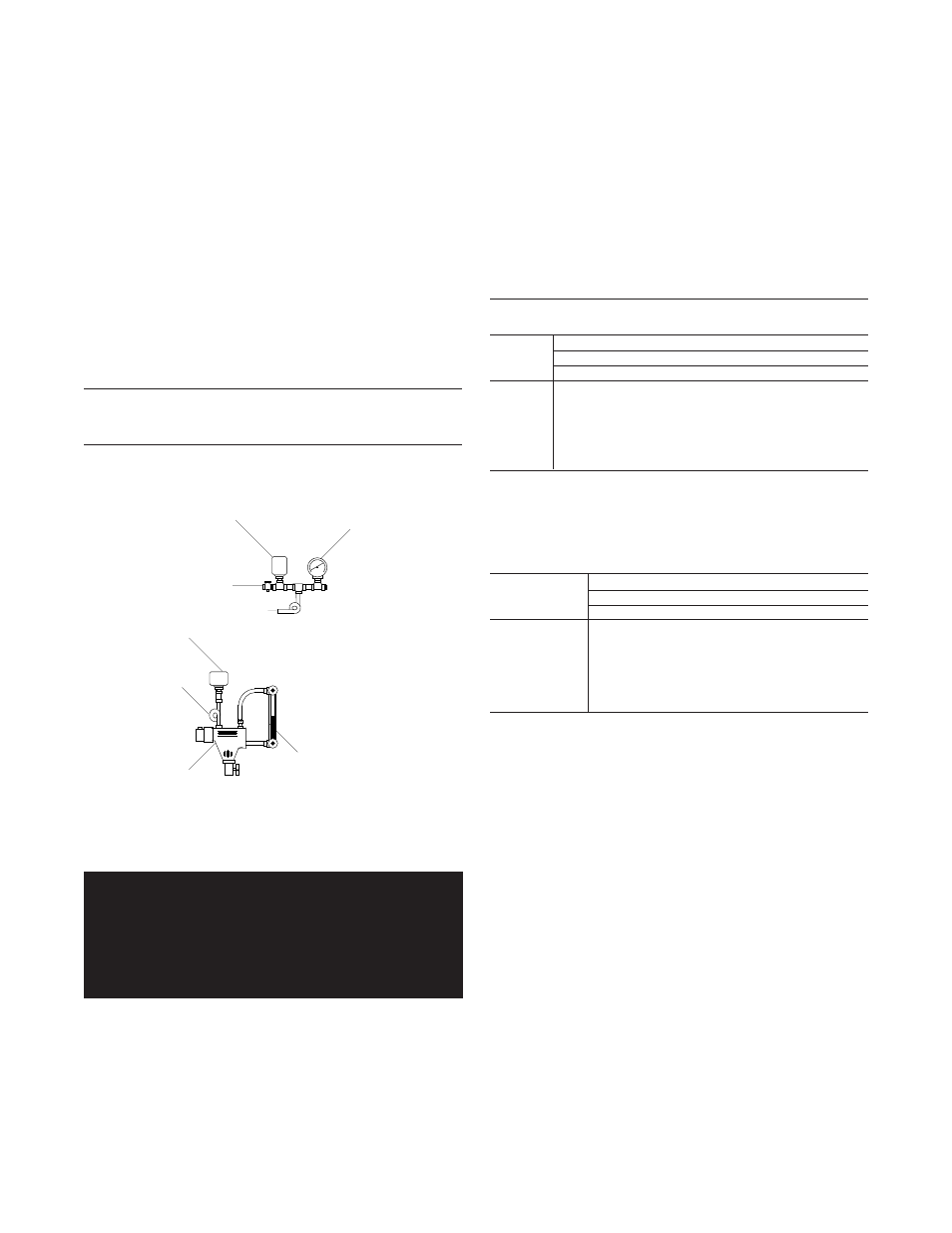
Assemble the control tree and low water cutoff as shown
in Figure 99. Use Figure 94 to locate the control tree
and low water cutoff on the boiler.
Table 5
Riser, Equalizer & Header Pipe Sizes
Boiler Model
Risers
Equalizer
Header
GB300-5 to -9
1 @ 3"
1-1/2"
3"
GB300-10 to -15
2 @ 3"
2"
4"
GB300-16 to -21
3 @ 3"
3"
5"
Figure 99
Steam Control Tree
GAS SUPPLY PIPING
WARNING: Check the boiler rating plate to make
sure that the boiler is for the type of gas that will
be used. If it isn’t, do not connect the boiler to
the gas supply. Failure to comply with this
warning can result in extensive property damage,
severe personal injury or death!
The GB300(S,W) boiler comes from the factory ready to
be piped to the gas supply. If for any reason the boiler is
not for the type of gas available at the installation site,
call the nearest Smith Cast Iron Boiler distributor to
resolve the problem.
STEAM
GAUGE
MANUAL RESET
HIGH LIMIT
PET COCK
SYPHON
GAUGE
GLASS
L.W.C.O.
(OPT.)
SYPHON
OPERATIG
CONTROL