Heating system piping, Page 35 – Smith Cast Iron Boilers GB300 User Manual
Page 35
GB300 BOILER INSTALLATION AND OPERATION INSTRUCTIONS
Page 35
HEATING SYSTEM PIPING
NOTE: The boiler jacket must be installed before
connecting the heating system piping and controls.
All heating system piping must be installed by a qualified
technician in accordance with the latest revision of the
ANSI/ASME Boiler and Pressure Vessel Code, Section
IV, and ANSI/ASME CSD-1, Standard for Controls and
Safety Devices for Automatically Fired Boilers. All
applicable local codes and ordinances must also be
followed. A minimum clearance of 1" must be maintained
between heating system pipes and all combustible
construction.
CAUTION: Improper piping of this boiler can cause
flooding and extensive property damage!
Ensure that the boiler is level from front to back and from
side to side. Use metal shims to level the boiler. NEVER
use wood, plastic or other combustible materials as
shims.
If a boiler is installed above any radiation elements it
must be fitted with a low water cutoff device.
WATER BOILER PIPING CONNECTIONS
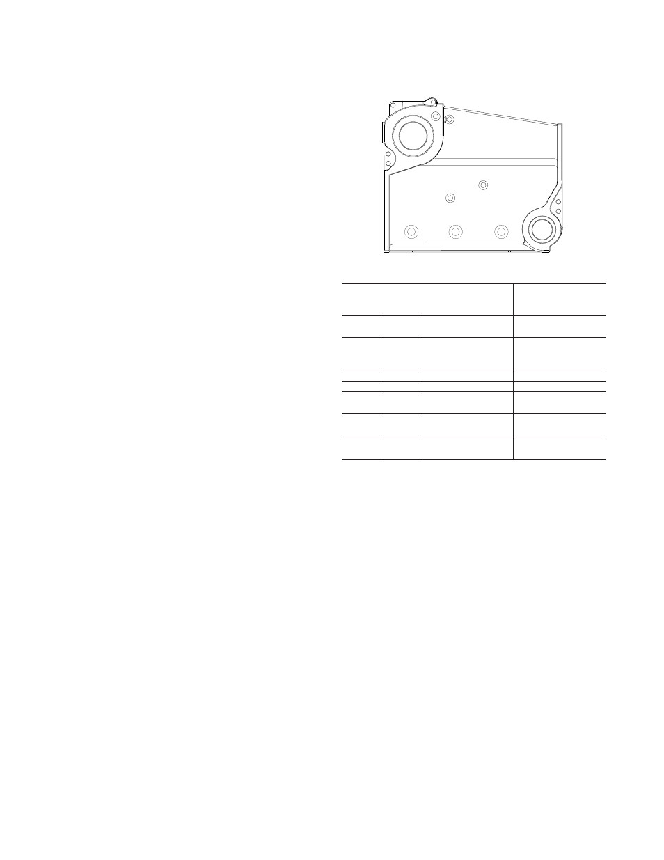
The supply and return connections should be sized to
suit the system, see Figure 94 & Table 4. Do not pipe
the supply from the bottom port or the return to the top
port, the boiler will not work properly.
Figure 94
Water & Steam Control Tapings
Tapping
Size
Water
Steam
1
4"
Supply & Optional
Optional Safty Valve
Tankless Heater
Location &
Skim Tapping
2
3"
Return & Boiler
Return & Boiler
Drain/Blowoff
Drain/Blowoff
3
1-1/2"
Water Relief Valve
Steam Relief Valve &
Optional Control
Tree Location
4
3/4"
Temp./Pressure Gauge
2
N/A
5
3/4"
High Limit
2
Gauge Glass
3
6
3/4"
Operating Control
2
Control Tree
(see Figure 99)
7
3/4"
Optional Probe
Optional Probe
LWCO
LWCO
3
8
1"
Optional Float
Optional Float
LWCO’s
LWCO’s
3
Notes:
1. The left end section contains the same tappings as the right end
section.
2. These controls must be located on the supply piping side of the
boiler.
3. These controls must be located on the steam equalizer piping
side of the boiler.
1
4
3
5
6
7
6
8
8
8
2