4. name and function of switch/indicator/etc – Sony BKPF-L753A User Manual
Page 8
1-2 (E)
BKPF-L753A
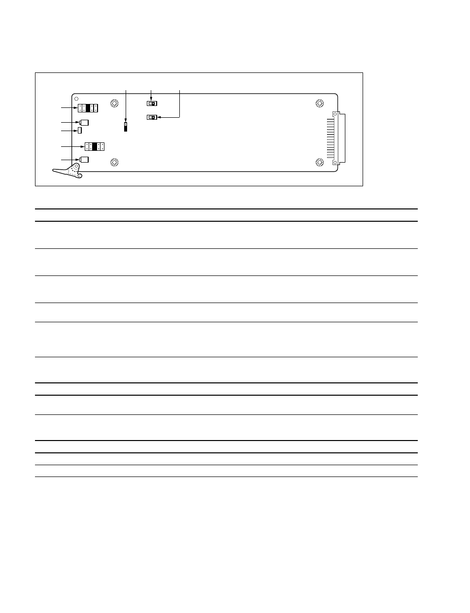
1-4. Name and Function of Switch/Indicator/etc.
Main Board (ADA-55 Board: Side A)
Switches/shorting plugs (Factory default settings are indicated by a
\
\
\
\
\
mark)
No. Ref. No. Name
Function
7
S1
AUDIO 1 600
Z
Selects the input impedance of the signal input to the AUDIO 1 connector.
OFF:
20 k
Z
\
ON:
600
Z
8
S2
AUDIO 2 600
Z
Selects the input impedance of the signal input to the AUDIO 2 connector.
OFF: 20 k
Z
\
ON:
600
Z
4
COR1
AUDIO 2 GAIN
Selects an input/output gain of the signal input to the AUDIO 2 connector.
(Valid only when COR3 is set to ST.)
+
8 dB
+
4 dB
\
0 dB
_
4 dB
_
8 dB
1
COR2
AUDIO 1 GAIN
Selects an input/output gain of the signal input to the AUDIO 1 connector.
+
8 dB
+
4 dB
\
0 dB
_
4 dB
_
8 dB
6
COR3
MONAURAL/STEREO Selects monaural or stereo mode of the analog audio signal input/output.
MO (Monaural): The signal input to the AUDIO 1 connector is distributed to eight outputs
\
ST (Stereo):
The each signal input to the AUDIO 1 and AUDIO 2 connectors is distributed to
four outputs
Indicator
No. Ref. No. Name
Color
Function
3
D1
POWER
Green/red
Green: A power supply of
±
12 V is normal
Red:
A power supply of
±
12 V is abnormal
Gain adjusting VR
No. Ref. No. Name
Function
5
RV3
AUDIO 2 FINE VR
Adjusts the gain of the signal input to AUDIO 2 connector within the
±
2 dB range.
2
RV4
AUDIO 1 FINE VR
Adjusts the gain of the signal input to AUDIO 1 connector within the
±
2 dB range.
n
At the factory-out, the gain adjusting VRs were adjusted to 0 dB. (the standard level
+4 dBm)
3
4
5
S1
S2
6
2
7
8
1
COR2
COR1
MO
RV4
RV3
D1
COR3
S T
+
8
+
4
0
_
4
_
8
+
8
+
4
0
_
4
_
8
1-4. Name and Function of Switch/Indicator/etc.