Assembly / pre-operation – Sears 917.370721 User Manual
Page 6
6
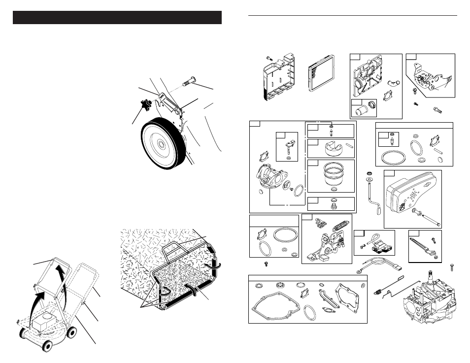
TO ASSEMBLE GRASS CATCH ER
1. Put grass catcher frame into grass bag with
rigid part of bag on the bottom. Make sure
the frame handle is outside of the bag top.
2. Slip vinyl bindings over frame.
NOTE: If vinyl bindings are too stiff, hold
them in warm water for a few minutes. If
bag gets wet, let it dry before using.
Frame
handle
Frame
opening
Vinyl
bindings
MOWING
POSITION
Lower handle
LIFT
UP
Operator
presence
control bar
Upper
handle
LIFT
UP
Handle
knob
Handle
bracket
Knob
Bolt
ASSEMBLY / PRE-OPERATION
Read these instructions and this manual in its entirety before you attempt to assemble or
operate your new lawn mower.
IMPORTANT: This lawn mower is shipped WITHOUT OIL OR GASOLINE in the engine.
Your new lawn mower has been as sem bled at the factory with the exception of those
parts left unassembled for shipping purposes. All parts such as nuts, washers, bolts, etc.,
nec es sary to complete the as sem bly have been placed in the parts bag. To ensure safe
and proper operation of your lawn mower, all parts and hard ware you assemble must be
tightened securely. Use the correct tools as necessary to ensure proper tightness.
TO INSTALL ATTACHMENTS
Your lawn mower was shipped ready to be
used as a mulcher. To convert to bagging or
discharging, see “TO CON VERT MOW ER”
in the Operation section of this man u al.
TO REMOVE MOWER FROM
CAR TON
1. Remove loose parts included with mower.
2. Cut down two end corners of carton
and lay end panel down fl at.
3. Remove all packing materials except
padding between upper and lower
handle and padding holding operator
presence control bar to upper handle.
4. Roll mower out of carton and check carton
thor ough ly for additional loose parts.
HOW TO SET UP YOUR MOW ER
TO UNFOLD HANDLE
IMPORTANT: Unfold handle carefully so
as not to pinch or damage control cables.
1. Raise lower handle section to operating
position and align hole in handle with one
of three height positioning holes.
2. Insert handle bolt through handle and
bracket and secure with knob.
3. Repeat for opposite side of handle.
4. Remove protective padding, raise up-
per handle section into place on lower
handle and tighten both handle knobs.
5. Remove any packing material from
around control bar.
Your lawn mower handle can be adjusted
for your mowing comfort. Refer to “AD-
JUST HANDLE” in the Service and Adjust-
ments section of this manual.
43
MODEL NUMBER 125K02-0658-E1
BRIGGS & STRATTON 4-CYCLE ENGINE
104
137
276
95
127
633
617
276
130
365
125
134
975
133
117
163
968
445
425
443
163
529
966
976
188
104
137
276
127
633
121 CARBURETOR OVERHAUL KIT
617
137
633
617
977 CARBURETOR
GASKET SET
163
163
134
81
613
300
222
97
668
276
358 ENGINE GASKET SET
12
3
20
51
585
7
163
524
668
842
617
334
851
333
202
209
356
562
505
227
616
404
615
922
621
923
745
48