JL Audio 1000/1 User Manual
Page 8
JL AUDIO 1000/1
15
14
JL AUDIO 1000/1
APPENDIX B:
Input Sensitivity Level Setting
JL Audio amplifiers utilizing the Regulated
Intelligent Power Supply (R.I.P.S.) allow delivery of
their rated power when connected to any load
impedance from 1.5 - 4
Ω per channel and when
connected to a charging system with any voltage
from 11 - 14.5V. This design is beneficial for many
reasons. One of these reasons is ease of setup.
Because each JL Audio amplifier will always deliver
the same amount of power within its operational
range of impedances and supply voltages, the
maximum, unclipped output is very predictable.
This makes setting the gain structure via the input
sensitivity controls very simple. Following the
directions below will allow the user to adjust the
input sensitivity of the amplifier(s) simply and easily
in just a few minutes using equipment which is
commonly available in installation bays.
Necessary Equipment
• Digital AC Voltmeter
• CD with a sine-wave test tone recorded at 0 dB
reference level in the frequency range to be
amplified (ex. 50 Hz for a subwoofer amplifier.
1 kHz for a midrange application). Do not use
attenuated test tones (-10 dB, -20 dB, etc.).
The Nine-Step Procedure
1) Disconnect the speaker(s) from the amplifier’s
“Subwoofer Output”connectors (you only need to
remove the negative or positive speaker wire).
2) Turn “Off ” all processing on the source unit
and amplifier (bass/treble, loudness, EQ, etc.).
3) Switch the “Input Voltage” to “Low” and
turn the “Input Sens.” control on the amplifier all
the way down.
4) Set the source unit volume to 3/4 of full
volume. If the amplifier is being driven by a source
unit’s dedicated subwoofer output, also adjust the
source unit’s subwoofer level control to 3/4 of
maximum output.This will allow for reasonable gain
overlap with moderate clipping at full volume.
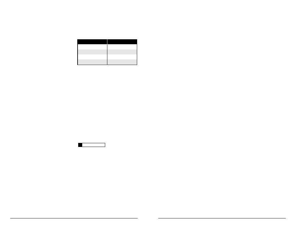
5) Using the chart below, determine the target
voltage for input sensitivity adjustment according to
the nominal impedance of the speaker system
connected to the amplifier output.
6) Verify that you have disconnected the
speakers before proceeding. Play a track with an
appropriate sine wave (within the frequency range
to be amplified) at 3/4 source unit volume.
7) Connect the AC voltmeter to the
“Subwoofer Output” connectors of the amplifier.
8) Increase the “Input Sens.” control until the
target voltage is delivered. If multiple subwoofer
amps are being used, set each one to the same
exact voltage and you have also level matched
them. If excessive voltage is read with the control
at minimum (full counterclockwise), switch the
“Input Voltage” to “High” and re-adjust.
9) Once you have adjusted each amplifier to its
maximum unclipped output level, reconnect the
speaker(s).The “Input Sens.” can now be adjusted
downward if the amplifier requires attenuation to
achieve the desired system balance.
Do not increase any “Input Sens.” setting in
the system beyond the maximum level established
during this procedure. Doing so will result in
audible distortion and possible speaker damage.
I M P O RTA N T
!
Nom. Impedance
Target AC Voltage
4
Ω (or higher)
63.2 V
3
Ω
54.7 V
2
Ω
44.7 V
1.5
Ω
38.7 V