JL Audio 1000/1 User Manual
Page 5
This is completely independent of the amplifier’s
internal filter and allows the user to match, stagger
or overlap the subwoofer low-pass filter frequency
of the amplifier crossover with the output filter’s
frequency for precise control and optimized
midbass performance.
If you would like to select the filter frequency
with a higher level of precision, consult
Appendix A: Chart A-2 (page 12) of this manual.
The signal level of the “Preamp Output” is
affected by the setting of the “Input Voltage Range”
switch (of the input section chosen by the
“Signal From” switch). See Appendix B (page 14)
for details on “Input Voltage” settings. All “slave”
amplifiers should get this switch set to “Low”.
See Appendix C (page 16) for details.
ADVANCED BASS CONTROL SECTION
The 1000/1 includes a versitile bass processing
section consisting of two primary components: a
fully variable, 24 dB per octave infrasonic filter and a
parametric, single-band equalizer.
1) “Infrasonic Filter”: The infrasonic filter is a
24 dB/octave high-pass filter, with a fully variable
cutoff frequency between 15 - 60 Hz. When set at
frequencies lower than 30 Hz, it conserves amplifier
power without audibly affecting the quality of the
sub-bass output. If set at frequencies higher that
30 Hz, there will be an audible effect, but one which
may be desirable for SPL competition purposes or
curve shaping of a bottom-heavy system.
With ported enclosures, the use of the
infrasonic filter is highly recommended to protect
the speaker(s) from excessive excursion below
box tuning. With sealed enclosures, the use of the
filter is less necessary, but can still help protect the
speaker system.
C AU T I O N
!!
If you would like to select the infrasonic filter
frequency with a higher level of precision, consult
Appendix A: Chart A-3 (page 13) of this manual.
The infrasonic filter can be completely defeated
by selecting the “Off” position on the “Mode”
switch.This bypasses all signal from flowing
through the circuit.
2) Parametric Bass Equalizer: The parametric
equalizer allows the used to select the center
frequency of the boost band as well as the
bandwidth (“Q”) of the boost band.
The “Q" control selects the bandwidth of the
boost around the center frequency. Lower numbers
pertain to wider bandwidths while higher number
pertain to narrower bandwidths.
The “Center Freq.” control selects the center
frequency of the boost bandwidth within a range of
20 - 80 Hz. If you would like to select the filter
frequency with a higher level of precision, consult
Appendix A: Chart A-4 (page 13) of this manual.
The “Boost” control determines how much
boost (in dB) you are adding to the bass signal.
A range of 0 - 15dB of boost is available.
The “Remote Bass Port” allows the connection
of an optional remote boost knob (the RBC-1)
that can be mounted in the front of the vehicle.
This optional control takes the place of the
“Boost” knob on the amplifier when connected
and bypasses the “Boost” control on the amplifier.
The “Advanced Bass Control” section will only
operate when the amplifier's filter is activated with
the “Amp LP Filter” switch in the “12dB” or
“24dB” position. It will not work with this switch in
the “Off” position.This is to prevent cascading the
processing of multiple amplifiers when configured
in a master/slave arrangement as shown in
Appendix C (page 16). If you are using an external
active crossover and would like to use the
“Advanced Bass Control” features, set the
“Amp LP Filter” switch on “12dB” and rotate the
frequency selection knob fully clockwise to the
“200 Hz” position.This will activate the “LF Boost”
and “Infrasonic Filter” controls without significantly
affecting the crossover point selected by the
external active crossover.
I M P O RTA N T
!
JL AUDIO 1000/1
9
The above hint is not “set-in-stone”…
You should always listen to the system carefully to
determine the best choice as vehicle acoustics and
other factors play a big role in choosing the most
appropriate filter slope.
2) Precise Frequency Selection: The filter
frequency markings on the front panel of the
amplifier are for reference purposes and are
generally accurate to within 1/3 octave or better.
If you would like to select the filter frequency with
a higher level of precision, consult Appendix A:
Chart A-1 (page 12) of this manual.This chart
gives you a more accurate frequency for each of
the forty detented positions of the frequency
selection control.This method can be very useful if
the amplifier is mounted in a location where you
can’t see the front panel markings easily.
3) Defeating the Amplifier Filter: The Low-
Pass filter can also be defeated completely, by
switching the “Mode/Slope” switch to the “Off”
position.This is useful if you are using an external
active crossover in the system. Keep in mind that
turning the internal crossover off also defeats the
“Advanced Bass Control” section processing
(see page 9 for details). With the internal
crossover turned off, the 1000/1’s upper
frequency response limit is 250 Hz, due to its
bass-specific Class D design.
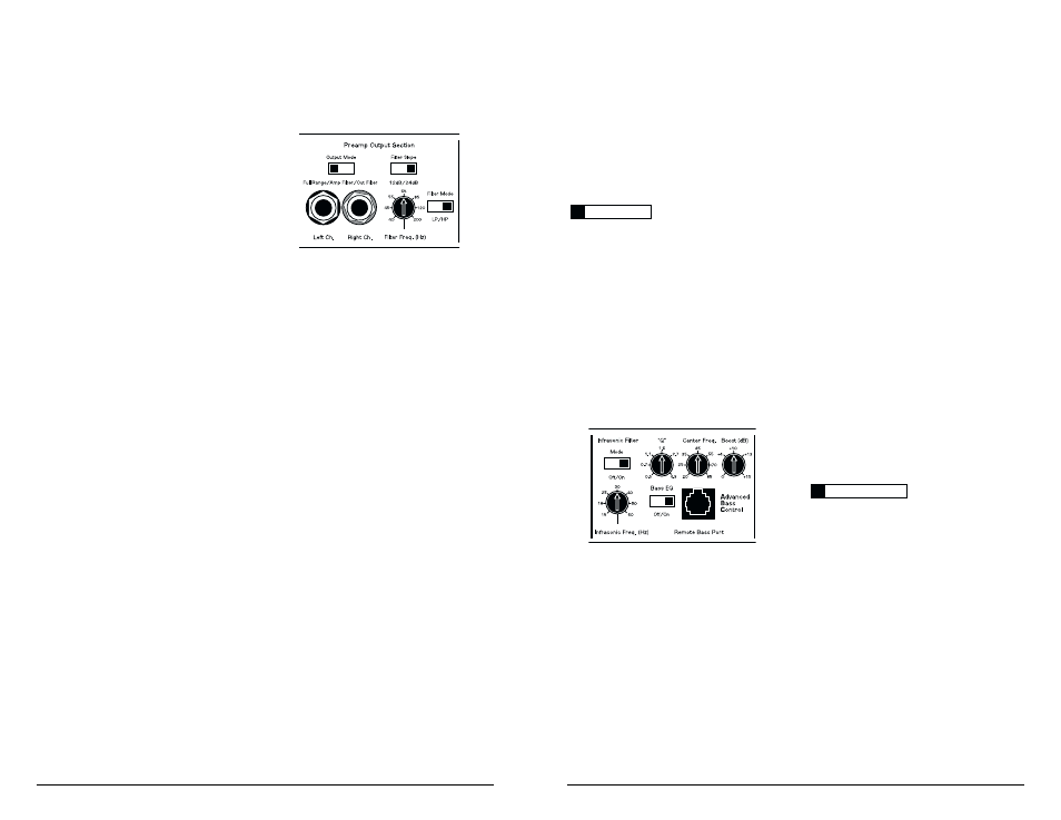
PREAMP OUTPUT SECTION
The 1000/1 incorporates a flexible preamp
output section, designed to make multiple amplifier
systems easy to set up.
The Preamp output can be configured in three
different “Output Modes”:
1) “Full-Range”: This is a pass-through mode
for the preamp output, delivering the same signal
that is being fed to the “Amplifier Input Section”
(If the input signal is full-range, the preamp output
will be full-range).This signal is not affected by the
“Advanced Bass Control” processing selected
for the amplifier.
2) “Amp Filter”: The preamp output delivers
the same signal that is feeding the 1000/1’s
amplifier section, including all the processing
induced by the “Amp LP Filter” and “Advanced
Bass Control” sections. This is primarily used for
running additional 1000/1’s in a “Slave”
configuration from the “Master” amplifier. For
detailed information on Master/Slave
configurations, see Appendix C (page 16). If the
“Output Mode” switch is in the “Amp Filter”
position and the “Amp LP Filter” switch is in the
“Off” position, there will be no output from the
preamp output jacks.The independent output filter
controls (“Filter Slope”, “Filter Freq” and “Filter
Mode”) are inactive in “Amp Filter” mode.
3) “Out Filter”: The preamp output is filtered by
a fully variable, active filter incorporated into the
output section and is not affected by the bass
control processing selected for the amplifier.
In “Out Filter” mode, the user can select:
a) High-pass (“HP”) or low-pass (“LP”) filtering by
way of the “Filter Mode” switch.
b) 12 dB/octave or 24 dB/ octave filter slope by way
of the “Filter Slope” switch.
c) A filter cutoff frequency between 40 - 200 Hz for
the preamp output signal by way of the “Filter
Control” switch.
8
JL AUDIO 1000/1