Connector panel, Controls and features – JVC DLA-HX2U User Manual
Page 9
9
Controls and Features
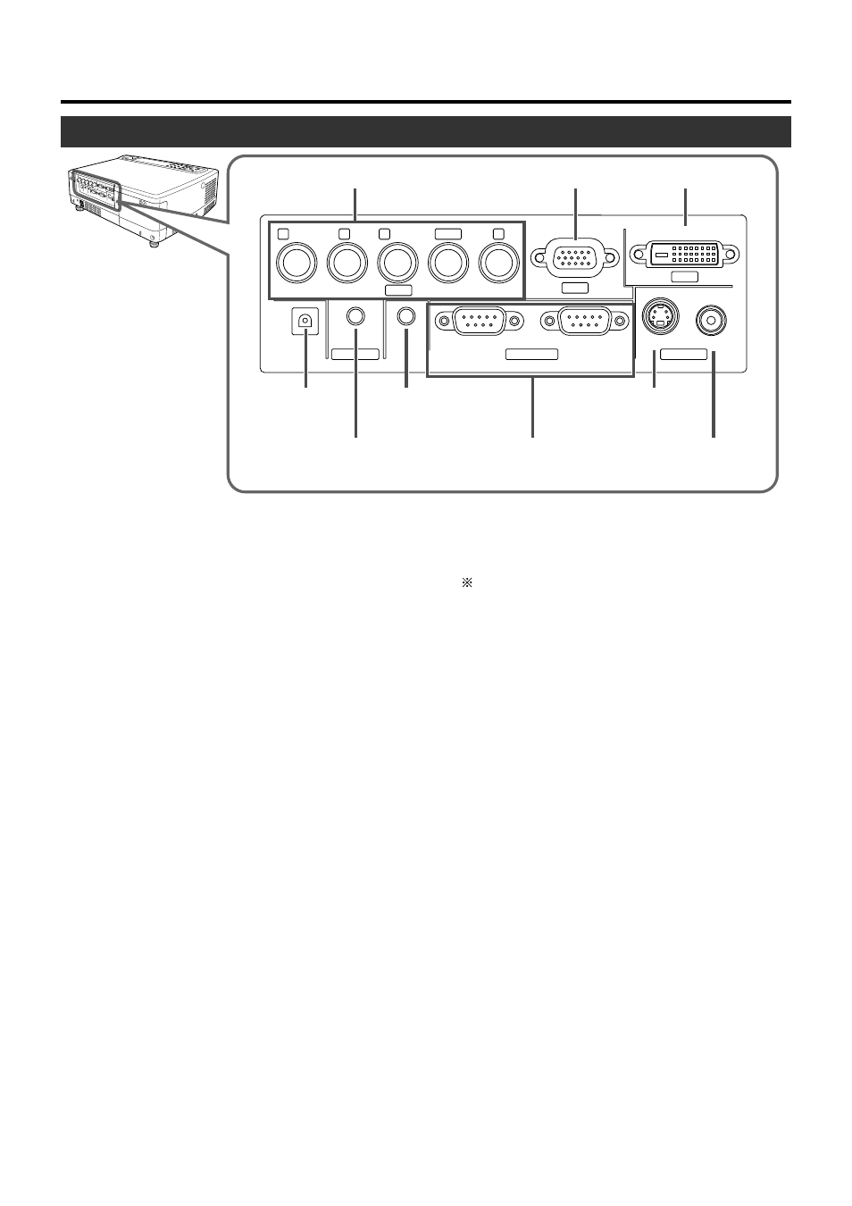
Connector Panel
1
[PC2] Input terminal (BNC x 5)
This is an input terminal for component signals (Y, C
B
, C
R
)
or DTV-format (Y, P
B
, P
R
) signals. Devices which have com-
ponent signal output terminals can be connected. This ter-
minal can also be used as multipurpose video input termi-
nals that allow input of the following signals: analog RGB
signals, vertical sync (V) signals, and horizontal sync (H)
signals/ composite signals (Cs). Devices which have ana-
log RGB signals output terminals can be connected.
(
☞ page 21, 22)
To use this terminal, the “PC2(BNC)” item in the “Options”
menu must be set correctly according to the input signals.
(
☞ page 39)
• Input of external sync signals is automatically detected.
Detection of H/V signals or Cs signals causes automatic
switching to external sync. The priority order is H/V>Cs.
• When computer signals are input, the uppermost edge
of the image may appear to bow if the sync signal input is
a composite sync (Cs) or G on sync signal. In this case,
please use separate sync signals for vertical sync (V)
and horizontal sync (H).
• Input signals of 720p (50Hz) are not supported.
2
[PC1] Input terminal (D-sub 3 rows 15 pin)
This is an input terminal dedicated to computer signals (RGB
Video signals and sync signals).
Connect the display output terminal of the computer to this
terminal. When a Macintosh computer is to be connected,
please use the conversion adapter (sold separately) for Mac.
(
☞ page 22)
• When computer signals are input, the uppermost edge
of the image may appear to bow if the sync signal input is
a composite sync (Cs) or G on sync signal. In this case,
please use separate sync signals for vertical sync(V) and
horizontal sync(H).
3
[PC3] Input terminal (DVI-D 24 Pin Single)
HDCP compatible video signals (480p, 576p, 720p 50/59/
60 Hz, 1080i 50/59/60 Hz) and input terminal for personal
computer (PC) signal. Connect the display output terminal
of the computer to this terminal. (
☞ page 22)
• The menu screen for HDCP compatible signal input is
the same as when PC input is selected.
4
[SCREEN TRIGGER] Terminal
The signal output for controlling roll-up screen that sup-
ports [SCREEN TRIGGER]. Outputs DC 12 V / max. 100 mA
when power is on.
(Tip = DC +12 V, Sleeve = Gnd)
Before using the supplied cable, read ‘How to use the
[SCREEN TRIGGER] terminal cable’ on page 5.
5
[AUDIO IN] (audio) Terminal (mini jack)
This is the audio input terminal for devices connected to
[PC1], [PC2], [PC3], [VIDEO] or [Y/C]. Connect the audio
output terminal of the device to this terminal.
(
☞ page 21, 22)
• When [PC1], [PC2], [PC3], [VIDEO] or [Y/C] input is be-
ing selected, the inputted audio signals will be reproduced
by the projector speaker.
(Audio output for this projector is monaural.)
6
[REMOTE] Terminal (stereo mini jack)
When the remote control is unable to work due to rear pro-
jection etc., the [REMOTE] terminal can be used to connect
an external sensor to the projector. The external sensor is
not generally sold. Please check with your authorized dealer.
7
[CONTROL RS232C IN/OUT] Terminal
(D-sub 9 Pin)
This is the RS-232C interface-specific terminal. The pro-
jector can be controlled by a computer connected exter-
nally. More than one projector can be controlled using both
the [RS-232C IN] and [RS-232C OUT] terminals.
(
☞ page 23)
• For details, please check with your dealer.
8
[Y/C] Input Terminal (Mini DIN 4 Pin)
This is the input terminal for Y/C (S-Video) signals. Con-
nect this terminal to the S-video output terminal of a video
deck, etc. (
☞ page 21)
9
[VIDEO] Input Terminal (RCA pin jack)
This is an input terminal for composite video signals. Con-
nect this terminal to the composite video output terminal of
a VCR, etc. (
☞ page 21)
R
P
R
/C
R
G
Y
B
P
B
/C
B
V
DVI
H/C
S
PC1
PC3
PC2
AUDIO IN
REMOTE
SCREEN
TRIGGER
RS-232C OUT
RS-232C IN
Y/C
VIDEO
CONTROL
VIDEO IN
2
[PC1] Input Terminal
8
[Y/C] Input
Terminal
3
[PC3] Input Terminal
1
[PC2] Input Terminal
9
[VIDEO] Input
Terminal
7
[CONTROL RS232C
IN/OUT] Terminal
5
[AUDIO IN]
Terminal
6
[REMOTE]
Terminal
4
[SCREEN
TRIGGER]
Terminal