Basic connections – JVC SR-VS30U User Manual
Page 12
Filename [VS30U_1-EN.fm]
Masterpage:Left
12
EN
Page 12
January 31, 2002 3:21 pm
INSTALLING YOUR NEW VCR
Basic Connections
It’s essential that your VCR be properly connected.
A
Check the contents.
Make sure the package contains all of the accessories
listed in “SPECIFICATIONS” on page 82.
B
Situate the VCR.
Place the VCR on a stable, horizontal surface.
C
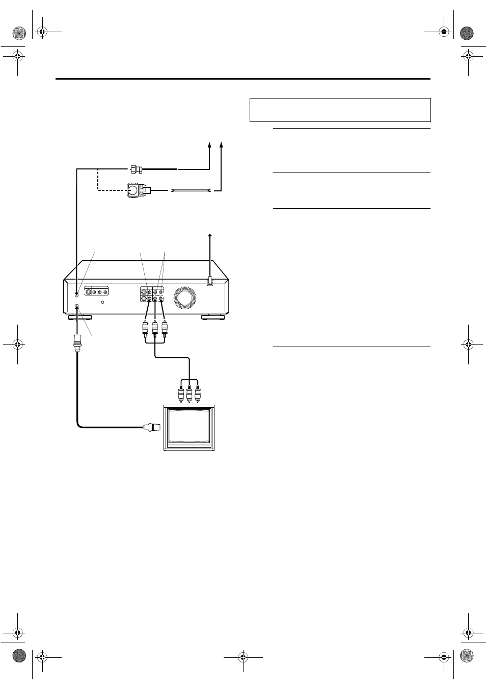
Connect the VCR to TV.
A Disconnect the TV antenna from the TV.
B Connect the TV antenna cable to the ANTENNA IN
connector on the rear panel of the VCR.
C Connect the supplied RF cable between the
ANTENNA OUT connector on the rear panel of the
VCR and the TV’s antenna terminal.
D Connect the supplied Audio/Video cable between the
AUDIO/VIDEO OUT connectors on the rear of the
VCR and the Audio/Video input connectors on the TV.
● Set your TV to AV mode.
● For switching the TV’s mode, refer to the instruction manual of
your television.
● To obtain high-quality S-VHS pictures, you can also use the
S-VIDEO connection described on page 13.
D
Connect the VCR to power source.
Plug the end of the AC power cord into an AC outlet.
● The clock and tuner channels will automatically be set when
the antenna is connected and when the AC power cord is first
connected to an AC outlet (
੬
pg. 14). (If “Auto” or “CH” is
displayed on the front display panel before the VCR is
powered on, the clock and tuner channels are being set
automatically. Wait for the time to be displayed on the front
display panel before turning on the VCR.)
Antenna or Cable
Matching Transformer
(not supplied)
Coaxial Cable
ANTENNA
IN
VIDEO
OUT
AC Outlet
RF Cable
(supplied)
Back of VCR
ANTENNA
OUT
AUDIO
OUT
Audio/Video Cable
(supplied)
Flat Feeder
TV
AC
Power
Cord
To 75 ohm Terminal
To Audio/Video
Input Connectors
THESE STEPS MUST BE COMPLETED BEFORE ANY
VIDEO OPERATION CAN BE PERFORMED.
VS30U_1-EN.fm Page 12 Thursday, January 31, 2002 3:33 PM