Connections on the back, Connection/installation, E-16 – JVC TK-C1480 User Manual
Page 9: E-17, Power supply, Control signal cables, Genlock connection
E-16
DC12V
AC24V
CLASS 2 ONL
Y(U TYPE)
ISOLA
TED POWER ONL
Y
(E TYPE)
TX
+
TX
-
RX
+
RX
-
AUX
Y/C OUT
SYNC IN
POWER
VIDEO OUT
GND
A
B
C
D
SEE INST-
RUCTION
MANUAL
1
+
-
2
Connect the DC 12 V or the AC 24 V power
supply to the DC 12V/AC 24V terminals. To
prevent connection errors or a cable
disconnection, we recommend the use of lug
plates for the connections.
The following table shows the connection
distances and connection cables provided
that 2-conductor VVF cables (vinyl-insulated
vinyl sheath cables) are used.
Maximum extension
(reference)
Conductor
diameter
100 m 260 m 410 m 500 m
1.0
∅mm 1.6∅mm 2.0∅mm 2.6∅mm
and more and more and more and more
Connections on the back
CONNECTION/INSTALLATION
MEMO
• If thin cables are used (i.e. with a high resistance), a significant voltage drop will occur
when the unit is at its maximum power consumption. Either use a thick cable to restrict
the voltage drop at the camera side to below 10%, or place the power supply near to the
camera. If voltage drop occurs during operation, the performance will be unstable.
• Attach the cable conductors so that they do not come into contact with the drop prevention
wires.
• Do not allow input from both a DC 12 V and AC 24 V power supply at the same time.
• When using a DC 12 V power supply, ensure that the polarities of the cable are correct.
• The AC 24 V power supply should conform to the following:
TK-C1480U Class 2 only
TK-C1480E Isolated power supply only
TK-C1481EG (AC230V)
Ⅲ Power supply
TK-C1480U and TK-C1480E (DC 12 V or 24 V)
Power cable connect to the commercial
AC230V outlet
CAUTION:
When you use this camera, the socket-out-
let shall be installed near equipment so
as to disconnect easily.
Y/C OUT
SYNC IN
POWER
VIDEO OUT
SEE INST-
RUCTION
MANUAL
E-17
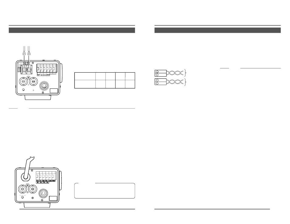
Ⅲ Control signal cables
These cables should be connected only when
it is required to control the camera using the
RS-442A or RS-485 signals. The use of 0.65
4-conductor twisted pair cables is recom-
mended. With these cables, the maximum ex-
tension distance is 1,200 m.
Connect to the other
side in pairs like this.
Connect to the other
side in pairs like this.
A
B
TX+
TX-
C
D
RX+
RX-
Ⅲ Genlock connection
With some systems, when the external sync
signal is a composite video or black burst sig-
nal genlocking by applying an external sync
input requires the horizontal phase (H
PHASE) and colour phase (SC COARSE) to
be adjusted.
MEMO
• Genlocking is not possible with a signal
containing too much jitter, such as a VCR
or videodisc playback signal.
• For details, consult a JVC authorized
dealer.