JVC HD-52Z575 User Manual
Page 33
(No.YA092B)1-33
4.7.3 MTS CIRUT
Item
Measuring
instrument
Test point
Adjustment part
Description
WHITE
BALANCE
(High light)
adjustment
Signal
generator
Remote
control unit
[1. ADJUST]
S030:R DRIVE
(Red drive)
S031:G DRIVE
(Green drive)
S032:B DRIVE
(Blue drive)
(1) Receive a NTSC all-white (75% white) pattern
signal.
(2) Set VIDEO STATUS to [STANDARD].
(3) Set ASPECT to [FULL].
(4) Set COLOR TEMPERATURE to [LOW].
(5) Select [1.ADJUST] from the SERVICE MENU.
(6) Fix one of < S030 > (Red drive), < S031 > (Green
drive) or < S032 > (Blue drive). Then, lower the other
two that are not fixed so that the all-white screen is
equally white throughout.
(7) Adjust one or more of < S030 > (R.DRIVE), < 031 >
(G DRIVE) and < 032 > (B DRIVE) to set values [128].
(8) Check that white balance is properly tracked from
low light to high light. If the white balance tracking is
deviated, adjust to correct it.
(9) Press the [MUTING] key to memorized the set
value.
Item
Measuring
instrument
Test point
Adjustment part
Description
MTS INPUT
LEVEL
adjustment
Remote
control unit
[1. ADJUST]
T001:IN LEVEL
(1) Select the [1.ADJUST] from the SERVICE MENU.
(2) Select the
(3) Set the
(4) Press the [MUTING] key to memorized the set
value.
MTS
SEPARATION
adjustment
TV audio
multiplex
Oscilloscope
Remote
control unit
[1. ADJUST]
T002: LOW SEP
T003: HIGH SEP
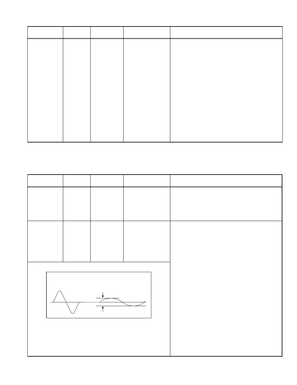
(1) Input stereo L signal (300Hz) from the TV audio
multiplex signal generator to the antenna terminal.
(2) Connect an oscilloscope to L OUTPUT pin of the
AUDIO OUT, and display one cycle portion of the
300Hz signal.
(3) Change the connection of the oscilloscope to R
OUTPUT pin of the AUDIO OUT, and enlarge the
voltage axis.
(4) Select
(5) Set the initial setting value of
(6) Adjust
element of the 300Hz signal will become minimum.
(7) Change the signal to 3kHz, and similarly adjust
(8) Press the [MUTING] key to memorized the set
value.
L-Channel
signal waveform
R-Channel
crosstalk portion
Minimum
1 cycle