Location and function of controls, Back panel – Jwin JV-DTV17 User Manual
Page 9
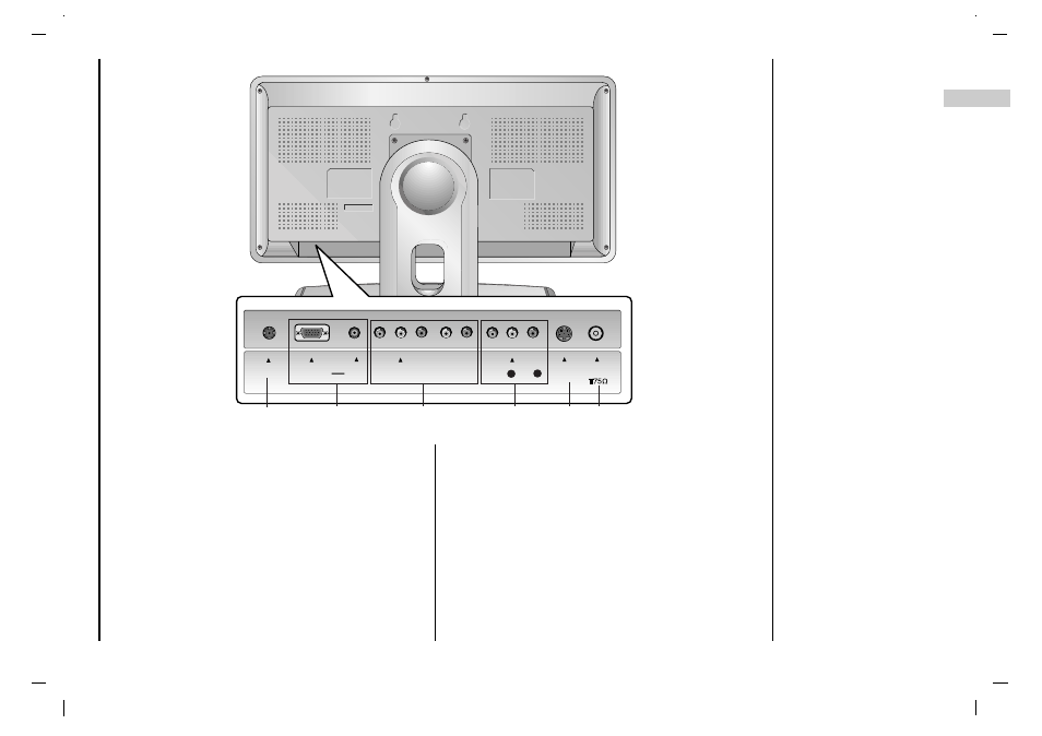
Location and function of controls
Back panel
9
EN
1. POWER CORD SOCKET
2. RGB INPUT(PC/DTV INPUT) / L/R IN
Connect the set output socket of the PERSONAL COM-
PUTER to this socket.
3. COMPONENT INPUT (480i/480p/720p/1080i) / AUDIO
INPUT
4. VIDEO/AUDIO INPUT
Connect the audio/video out sockets of the VCR to AV
sockets of the set
5. S-VIDEO INPUT
connect video out from an S-VIDEO VCR to the S-
VIDEO input.
6. AERIAL SOCKET
connect the RF socket of the VCR to the aerial sockets.
(
)
DC-12V
DC-12V
RGB IN
RGB IN
(PC/DTV INPUT)
(PC/DTV INPUT)
L/R IN
L/R IN
S-VIDEO
S-VIDEO
ANT
ANT IN
IN
Y
Y Pb Pr
Pb Pr
(COMPONENT
(COMPONENT INPUT)
INPUT)
R
R
L
L
VIDEO
VIDEO
AUDIO
AUDIO
LL
R
R
1
2
3
5
6
4