0 circuit board diagrams, 1 north american j-230, j-270 and j-280 models, J4 f1 – Jacuzzi J - 230 User Manual
Page 48
J-200 Series
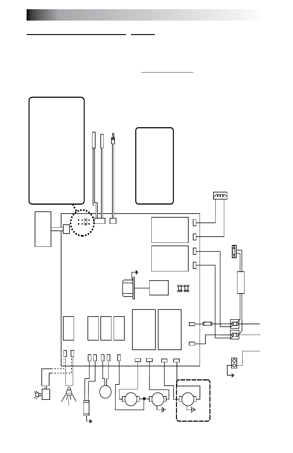
16.0 Circuit Board Diagrams
16.1
north american J-230, J-270 and J-280 Models
This wiring diagram is used for all J-230, J-270 and J-280 240V
60 Hz North American spa models With or Without the Circulation Pump
Option.
Optional Stereo
Power Supply
O
ZO
N
AT
O
R
(O
PT
IO
N
AL
)
O
3
GRN
TB1
Standard 240 V
AC, 3-W
ire Connection (60Hz, 1-Phase Service)
USE COPPER CONDUCT
ORS ONL
Y. WIRE SIZE MUST
BE
APPROPRIA
TE PER NEC
AND/OR LOCAL
CODES
RED
RED
J6
BLK J5
WHT
WHT
WHT
RED
BLK
BLK
BLK
WHT
BLK
RED
RED
BLK
BLK
BLK
2
1
FLOW SWITCH
HI - LIMIT
/ FREEZE SENSOR
TEMPERA
TURE SENSOR
J1
J2
J3
F1 30A, 250V SC-30
PU
M
P
1
PU
M
P
2
TR
AN
SF
O
R
M
ER
24
0
VA
C
J4
F1
JP1
4 2
3 1
6
5
8
7
7
6
2
4
HI
HI
LO
C
C
on
tr
ol
P
an
el
CIRC. PUMP
J20
K1
K2
K3
K4
K5
K6
K7
K8
J21
J1
1
J12
J13
J14
J15
J16
J17
J18
J19
J7
J8
J9
J10
This device complies with Part 15 of the
FCC rules. Operation is subject to the
following two conditions:
1.
This device may not cause harmful
interference.
2.
This device must accept any inteferenc
e
received including interference that ma
y
cause undesired operation.
Heater 5.5 kW 240 V
AC
WHT
BLK
WHT
BLK
Standard
Footwell
Light
* Shown
with Optional
Circulation
Pump
Optional
LED Ligh
ting
Sy
st
em DCU
OR
Logic Jumper Settings (Factory Defaults Shown)
JP1 1-2
ON
= 40A
Logic
JP1 1-2
OFF
= 50A
Logic (Factory Default Setting)
JP1 3-4
ON
= 2 Pump Operation (Not used on J-230)
JP1 3-4
OFF
= 1 Pump Operation
JP1 5-6
ON
= 60A
Logic (Remove JP1 1-2 Jumper)
(Not used on J-230)
JP1 5-6
OFF
= Leave of for 40A
or 50A
Logic
JP1 7-8
ON
= °C
Temperature Display
JP1 7-8
OFF
= °F
Temperature Display
Not used on J-230
44