Rear panel, Index (cont.) – JVC HM-DH5U User Manual
Page 8
Masterpage:Left-FullCol
8
EN
Filename [HM-DH5U_Eng.fm]
INDEX (cont.)
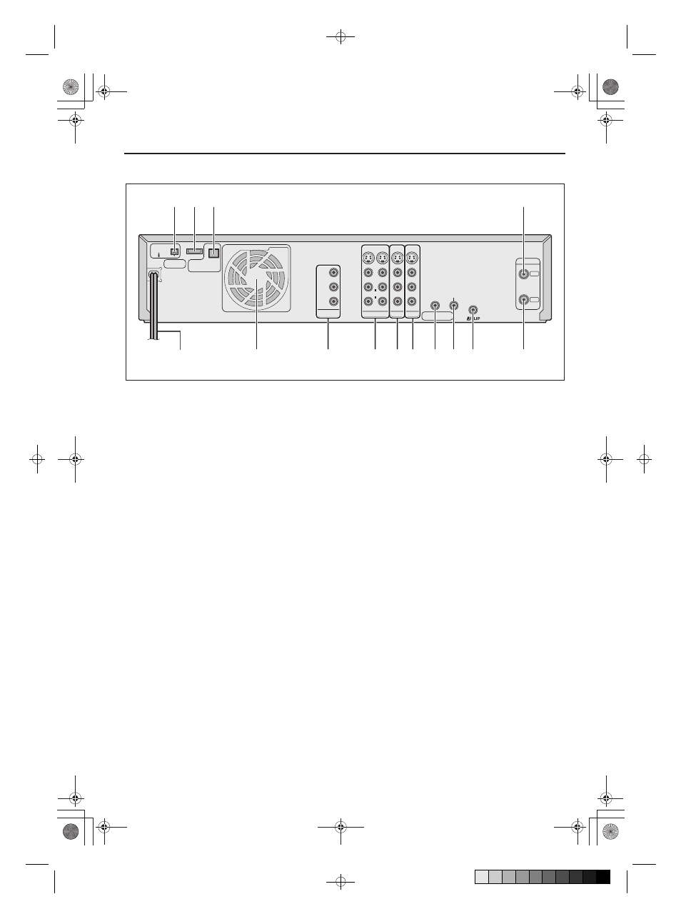
Rear panel
A AC power cord : A page 13
B Cooling fan
•
This prevents the temperature from rising inside the
VCR. Do not remove it.
•
Install the VCR so as not to block the area around
the cooling fan.
•
The cooling fan may be activated even if the unit is
turned off in the following case;
— if the Auto Clock Set and Auto Tuner Set have
not been completed automatically by the Plug &
Play setting. (A page 16)
Setting the clock manually (A page 19) will
turn off the cooling fan.
C [COMPONENT VIDEO OUT] connectors :
A page 13
D [S VIDEO]/[AUDIO]/[VIDEO OUTPUT] connectors :
A page 13
E [S VIDEO]/[AUDIO]/[VIDEO INPUT] connectors
(L-1) : A page 15, 74
F [S VIDEO]/[AUDIO]/[VIDEO INPUT] connectors
(L-2) : A page 15, 74
G [REMOTE PAUSE/AV COMPULINK] terminal
•
[REMOTE PAUSE] terminal : A page 75
•
[AV COMPULINK] terminal : A page 67
H [CABLE BOX] Controller connector : A page 22, 25
I [JLIP] terminal : A page 69
J [ANTENNA OUT] terminal : A page 13
K [i.LINK IN/OUT], [DV IN] Connector (i.Link*) :
A page 72
*
i.Link refers to the IEEE1394-1995 industry
specification and extensions thereof. The A logo is
used for products compliant with the i.Link
standard.
L [HDMI OUT] connector: A page 13, 15
M [OPTICAL] terminal : A page 13, 64
N [ANTENNA IN] terminal : A page 13
REMOTE PAUSE/
AV COMPULINK
CABLE BOX
VHF/UHF
IN
ANTENNA
ANTENNA
L-2
PCM/STREAM
DIGITAL AUDIO OUT
OPTICAL
P
B
/C
B
P
R
/C
R
Y
COMPONENT
VIDEO OUT
OUTPUT
HDMI OUT
D-THEATER
REGION 1
i.LINK IN/OUT
DV IN
L-1
S400
INPUT
S-VIDEO
VIDEO
L
AUDIO
R
S-VIDEO
VIDEO
L
AUDIO
R
OUT
A
B
C
D E F G H
J
N
K L M
I
HM-DH5U_Eng.fm Page 8 Tuesday, June 1, 2004 4:12 PM
(X:100.0%, Y:100.0%)
Created with Grafikhuset CMYK PDF Creator for keiji tanaka at Sanwa Document Services P/L.