JL Audio HD600/4 User Manual
Page 6
10 | JL Audio - HD600/4 Owner’s Manual
11
CrossoVer Controls
Crossovers are groups of electronic filters
designed to control the frequency ranges
that each speaker in a system will be tasked
with reproducing. Proper crossover setup is
critical to sound quality and reliability.
The HD600/4 has two individual filters,
one for the “Front” channels and the
other for the “Rear” channels. Each can be
configured as a high-pass filter (attenuates low
frequencies) or as a low-pass filter (attenuates
high frequencies). Additionally, the user can
select from a shallow (12dB/octave) filter slope
or a more aggressive (24dB/octave) slope.
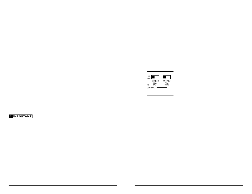
Each Channel Control section contains
identical crossover filter controls.
1) “Filter Mode” Control: this switch allows you
to configure the filter for that Channel Pair
into one of two filter types.
“Off”: Defeats the filter completely, allowing
the full range of frequencies present at the
inputs to feed that pair of channels. This
is useful for systems utilizing outboard
crossovers or requiring full-range reproduction
from that pair of channels.
“HP” (High-Pass): Configures the
CH 1&2 filter to attenuate frequencies
below the selected filter frequency.
Useful for connection of component
speakers in a bi-amplified system.
“LP” (Low-Pass): Attenuates frequencies
above the selected filter frequency.
Useful for connection of subwoofer(s)
in a bi-amplified system.
2) “Filter Slope” Control: This switch allows you
to select from two filter slopes.
“12dB”: Configures the filter to attenuate
frequencies above or below the selected
filter frequency at a rate of 12 dB per octave
(Butterworth alignment).
“24dB”: Configures the filter to attenuate
frequencies above or below the selected
filter frequency at a rate of 24 dB per octave
(Linkwitz-Riley alignment).
Depending on the speaker system and the
vehicle, different filter slopes may be required to
produce a smooth transition between the sound
of different speakers in the system.
In high-pass mode, the sharper “24dB” setting
will do a better job of protecting small speakers
with limited power handling. In low-pass
mode, the “24dB” setting can also help by more
aggressively removing lower midrange output
from a subwoofer system.
The shallower “12dB” octave setting
allows for more output overlap between
the speakers being crossed over. In many
cases, this will result in a smoother “blend”
or transition between speaker systems.
Experiment to find the slope or combination
of slopes which best matches the acoustic
requirements of your system.
3) “Filter Freq. (Hz)” Control:
This control selects the frequency at which the
filter begins to attenuate the signal and refers
specifically to the frequency at which output
has been attenuated by -3dB.
The filter frequency markings surrounding this
rotary control are for reference purposes and are
generally accurate to within 1/3 octave or better. If
you would like to select the filter cutoff frequency
with a higher level of precision, consult the charts
in Appendix B (page 18) of this manual.
“input Voltage” switch
A wide range of signal input voltages can
be accommodated by each of the HD600/4’s
differential-balanced inputs (200mV – 8V RMS).
This wide range is split up into two sub-ranges,
accessible via the “Input Voltage” switches located
in each input section of the amplifier. Be aware
that each input section’s “Input Voltage” switch
will have to be configured, regardless of how many
input cables are actually feeding the amplifier.
The “Low” position on each “Input
Voltage” switch selects an input sensitivity
range between 200mV and 2V. This means that
the “Input Sens.” rotary control will operate
within that voltage window. If you are using
an aftermarket source unit, with preamp-level
outputs, this is most likely the position that
you will use (regardless of what voltage output
capability is claimed by the source unit).
The “High” position on each “Input Voltage”
switch selects an input sensitivity range between
800mV and 8V. This is for use with speaker-level
outputs from source units and small amplifiers
found in many OEM (factory-installed) systems.
To use speaker-level sources, splice the speaker
output wires of the source unit or small amplifier
onto a pair of RCA plugs for each input pair
or use the JL Audio ECS Speaker Wire to RCA
adaptor (XB-CLRAIC2-SW).
The output of the amplifier decreases for a
given input voltage when the “Input Range”
switch is placed in the “High” position. The
output increases with the switch in the “Low”
position. While this may sound counter-
intuitive, it is correct as described.
“input sens.” Control
Located next to the “Input Voltage” switch
in each input section is a rotary control labeled
“Input Sens.”. Once the appropriate “Input
Voltage” range has been selected, this control
can be used to match the source unit’s output
voltage to the input stage of each pair of amplifier
channels for maximum clean output. Rotating the
control clockwise will result in higher sensitivity
(louder for a given input voltage). Rotating the
control counter-clockwise will result in lower
sensitivity (quieter for a given input voltage). To
properly set each pair of amplifier channels for
maximum clean output, please refer to Appendix
C (pages 18, 19) in this manual.
After using this procedure, you can then adjust
the relative level of each channel pair by adjusting
the input sensitivity downward on either or both
channel pairs, if they require attenuation to
achieve the desired system balance.
Do not increase the “Input Sens.” setting for
any amplifier in the system beyond the maximum
level established during the procedure outlined in
Appendix C (pages 18, 19). Doing so will result in
audible distortion and possible speaker damage.
Be aware that both “Input Sens.” adjustments
will have to be made, regardless of how many
input cables are feeding the amplifier. These
controls will allow you to set the appropriate
relative levels for the “Front” channels relative
to the “Rear” channels and any other amplifier
channels in the system.