JL Audio HD600/4 User Manual
Page 10
18 | JL Audio - HD600/4 Owner’s Manual
19
the nine-step Procedure
(follow this procedure for each pair of channels)
1) Disconnect the Speaker Connector Plugs.
2) Turn off all processing on the source unit
(bass/treble, loudness, EQ, etc.). Set fader
control to center position and subwoofer
level control to 3/4 of maximum (if
used to drive the HD600/4). Disconnect
the HD-RLC Remote Level Control
temporarily (if one is being used).
3) Switch the “Input Voltage” to “Low” and
turn the “Input Sens.” control on both sets of
channels all the way down.
4) Set the source unit volume to 3/4 of full
volume. If either set of channels is being
driven by a source unit’s dedicated subwoofer
output, also adjust the source unit’s subwoofer
level control to 3/4 of maximum output. This
will allow for reasonable gain overlap with
moderate clipping at full volume.
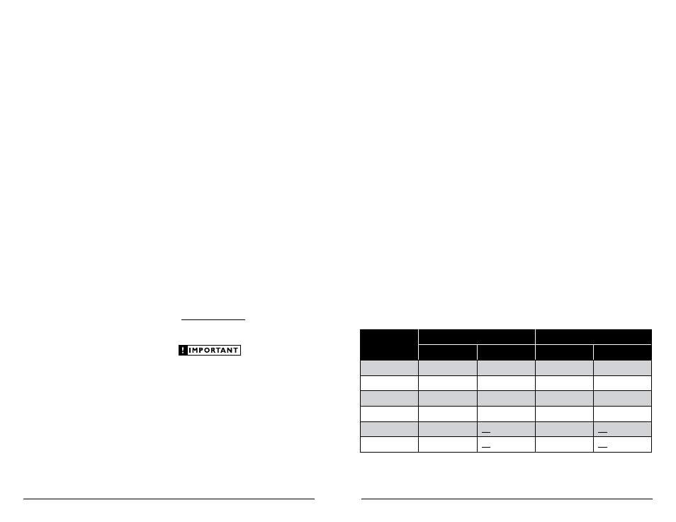
5) Using the chart below, determine the
target voltage for input sensitivity
adjustment according to the nominal
impedance of the speaker system
connected to each set of outputs.
6) Verify that you have disconnected the Speaker
Connector Plugs before proceeding. Play a
track with an appropriate sine wave (within the
frequency range to be amplified by each set of
channels) at 3/4 source unit volume.
7) Connect the AC voltmeter to the “Front
Speaker Outputs” or “Rear Speaker Outputs”
connectors of the amplifier. If the channel pair
is operating in stereo, it is only necessary to
measure one channel in the pair. If bridged,
make sure you test the voltage at the correct
connectors (L+ and R–).
8) Increase the “Input Sens.” control until
the target voltage is delivered for that set
of channels. If excessive voltage is read
on either set of channels with the control
at minimum (full counterclockwise),
switch the appropriate “Input Voltage”
switch to “High” and re-adjust.
9) Once you have adjusted each set of channels to
its maximum unclipped output level, reconnect
the speaker(s). The “Input Sens.” controls can
now be adjusted downward if either or both
sets of channels requires attenuation to achieve
the desired system balance.
nom.
impedance
Front CHannels
rear CHannels
stereo
bridged
stereo
bridged
8Ω
24.5 V
49.0 V
24.5 V
49.0 V
6Ω
24.5 V
42.4 V
24.5 V
42.4 V
4Ω
24.5 V
34.6 V
24.5 V
34.6 V
3Ω
21.2 V
30.0 V
21.2 V
30.0 V
2Ω
17.3 V
not recommended
17.3 V
not recommended
1.5Ω
15.0 V
not recommended
15.0 V
not recommended
aPPendix b:
Precise Frequency selection Chart
“Filter Freq”
detent
Panel
actual
number
marking
Freq.
Full counter-clockwise: 53
01 . . . . . . . . . . . “50”. . . . . . . . . . . .53
02 . . . . . . . . . . . . . . . . . . . . . . . . . . . .53
03 . . . . . . . . . . . . . . . . . . . . . . . . . . . .53
04 . . . . . . . . . . . . . . . . . . . . . . . . . . . .53
05 . . . . . . . . . . . . . . . . . . . . . . . . . . . .54
06 . . . . . . . . . . . . . . . . . . . . . . . . . . . .56
07 . . . . . . . . . . . . . . . . . . . . . . . . . . . .58
08 . . . . . . . . . . . “60”. . . . . . . . . . . .60
09 . . . . . . . . . . . . . . . . . . . . . . . . . . . .62
10 . . . . . . . . . . . . . . . . . . . . . . . . . . . .64
11 . . . . . . . . . . . . . . . . . . . . . . . . . . . .66
12 . . . . . . . . . . . . . . . . . . . . . . . . . . . .68
13 . . . . . . . . . . . . . . . . . . . . . . . . . . . .71
14 . . . . . . . . . . . . . . . . . . . . . . . . . . . .74
15 . . . . . . . . . . . . . . . . . . . . . . . . . . . .76
16 . . . . . . . . . . . “80”. . . . . . . . . . . .80
17 . . . . . . . . . . . . . . . . . . . . . . . . . . . .83
18 . . . . . . . . . . . . . . . . . . . . . . . . . . . .87
19 . . . . . . . . . . . . . . . . . . . . . . . . . . . .91
20 . . . . . . . . . . . . . . . . . . . . . . . . . . . .94
21 . . . . . . . . . . . . . . . . . . . . . . . . . . . .99
22 . . . . . . . . . . . . . . . . . . . . . . . . . . . 104
23 . . . . . . . . . . . . . . . . . . . . . . . . . . . 109
24 . . . . . . . “12 o’clock”. . . . . . . 115
25 . . . . . . . . . . . . . . . . . . . . . . . . . . . 121
26 . . . . . . . . . . . . . . . . . . . . . . . . . . . 128
27 . . . . . . . . . . . . . . . . . . . . . . . . . . . 137
28 . . . . . . . . . . . . . . . . . . . . . . . . . . . 147
29 . . . . . . . . . . . . . . . . . . . . . . . . . . . 160
30 . . . . . . . . . . . . . . . . . . . . . . . . . . . 174
31 . . . . . . . . . . . . . . . . . . . . . . . . . . . 191
32 . . . . . . . . . . . . . . . . . . . . . . . . . . . 211
33 . . . . . . . . . . “250” . . . . . . . . . . 236
34 . . . . . . . . . . . . . . . . . . . . . . . . . . . 269
35 . . . . . . . . . . . . . . . . . . . . . . . . . . . 309
36 . . . . . . . . . . . . . . . . . . . . . . . . . . . 369
37 . . . . . . . . . . . . . . . . . . . . . . . . . . . 443
38 . . . . . . . . . . “500” . . . . . . . . . . 484
39 . . . . . . . . . . . . . . . . . . . . . . . . . . . 525
Full-clockwise: 528
aPPendix C:
input sensitivity level setting
JL Audio amplifiers utilizing the Regulated
Intelligent Power Supply (R.I.P.S.) allow
delivery of their rated power when connected
to any load impedance from 1.5 - 4Ω per
channel and when connected to a charging
system with any voltage from 11 - 14.5V.
This design is beneficial for many reasons.
One of these reasons is ease of setup.
Because each JL Audio amplifier will
always deliver the same amount of power
within its operational range of impedances
and supply voltages, the maximum,
unclipped output is very predictable.
This makes setting the gain structure via the
input sensitivity controls very simple. Following
the directions below will allow the user to adjust
the input sensitivity of the amplifier(s) simply
and easily in just a few minutes using equipment
which is commonly available in installation bays.
necessary equipment
• Digital AC Voltmeter
• CD with a sine-wave test tone recorded at
0 dB reference level in the frequency range
to be amplified for that set of channels
(50 Hz for subwoofer channels, 1 kHz for
a midrange application). The CleanSweep®
Calibration Disc contains the appropriate
test tones and is available for sale at
http://store.jlaudio.com Do not use attenuated
test tones (-10 dB, -20 dB, etc.).
Do not increase any “Input Sens.” setting in
the system beyond the maximum level
established during this procedure. Doing so
will result in audible distortion and possible
speaker damage.
It will be necessary to re-adjust the “Input
Sens.” for the affected channels if any equalizer
boost is activated after setting the “Input
Sens.” with this procedure. This applies to any
EQ boost circuit, source unit tone controls or EQ
circuits. EQ cuts will not require re-adjustment.