Invacare 1085144 User Manual
Page 4
4
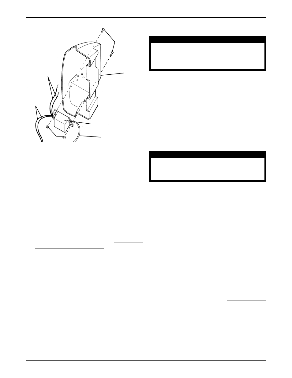
Installing the Battery Connector (FIGURE 7)
CAUTION
The BLUE (-) and YELLOW (+) wires MUST
be installed properly, otherwise, serious
damage to the electrical system of the
bath lift may occur.
1. Position the BLUE (-) wire through the FRONT hole
and the YELLOW (+) wire through the REAR hole
as shown in DETAIL "D" of FIGURE 7.
2. If necessary, loosen, but do not remove the two
(2) flat screws in the battery connector (DETAIL
"E").
3. Visually inspect the battery connector to find the
POSITIVE (+) and NEGATIVE (-) channels. Refer
to DETAIL "E" of FIGURE 7.
4. Insert the bare end of the YELLOW (+) wire into
the POSITIVE (+) channel.
CAUTION
DO NOT tighten the flat screw onto the
insulated portion of the wire. Ensure the
screw secures the bare wire ONLY.
5. Tighten the flat screw to secure the wire to the battery
connector. Refer to DETAIL "F" of FIGURE 7.
6. Repeat STEPS 4 - 5 to install the BLUE (-) wire
into the NEGATIVE (-) channel.
7. Ensure BOTH wires are securely installed in the
battery connector.
NOTE: If installed properly, the wires should not pull
out of the battery connector when gently tugged.
8. Position the battery connector on the motor shroud
with the flared end on the bottom as shown in FIG-
URE 7.
9. Align the mounting holes of the battery connector
with the mounting holes of the motor shroud.
10. Secure the battery connector to motor shroud with the
two (2) mounting screws and nuts. Tighten securely.
11. Install the motor shroud. Refer to INSTALLING THE
MOTOR SHROUD in this instruction sheet.
Installing NEW Current Limit Device
(FIGURE 6)
1. Position the NEW current limit device on the in-
side of the motor shroud with the blue and yellow
battery connector wires towards the REAR of the
shroud and the pendant cable towards the FRONT
of the shroud as shown in FIGURE 6.
2. Align the mounting holes of the current limit device
and the motor shroud and secure with the two (2)
existing mounting screws and nuts. Tighten se-
curely.
3. Install the battery connector. Refer to INSTALLING
THE BATTERY CONNECTOR in this instruction
sheet.
Mounting
Screws
BLUE and
YELLOW
Battery
Connector
Wires
Spade
Connector
Wires
Pendant Cable
Current Limit Device
Nuts
Motor
Shroud
FIGURE 6 - REMOVING CURRENT LIMIT
DEVICE
FRONT
REAR