Invacare 9000 XDT User Manual
Page 4
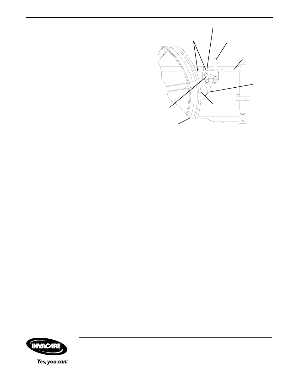
Wheel Lock
Handle
Bolt and Locknut
Mounting
Positions
Wheel
Lock
Shoe/
Shoe
Extension
5/32 and
5/16-inches
Rear
Wheel
FIGURE 7 - ADJUSTING THE PATIENT
OPERATED WHEEL LOCK
Wheel
Lock
Wheelchair
Frame
ADJUSTING THE PATIENT
OPERATED WHEEL LOCK (FIGURE 7)
NOTE: Refer to the INSTALLATION WARNING in the
SAFETY SUMMARY section of this instruction sheet.
NOTE: If wheels are pneumatic, before adjusting or re-
placing the wheel lock assemblies, ensure that the tires
are inflated to the recommended p.s.i. The recommended
tire pressure is located on the side wall of the tire.
1. Loosen the bolt and locknut that secure the wheel
lock assembly to the wheelchair frame.
2. Adjust the position of wheel lock until the measure-
ment between the rear wheel and the wheel lock shoe
or shoe extension is between 5/32 and 5/16-inches.
NOTE: If a measurement between 5/32 and 5/16-inches
cannot be achieved, remove the bolt and locknut that
secure the wheel lock to the wheelchair and mount the
wheel lock in one (1) of two (2) mounting positions.
3. Securely tighten the bolt and locknut.
4. Engage the wheel lock and push it against the wheel-
chair to determine if the wheel lock engages the wheel
lock shoe enough to hold the wheelchair.
5. Repeat STEPS 1-4 until the wheel lock holds the
wheelchair.
6. Repeat STEPS 1-5 for the opposite wheel lock.
Invacare Corporation
www.invacare.com
USA
Canada
One Invacare Way
5970 Chedworth Way
Invacare and "Yes, you can" are trademarks of Invacare
Elyria, Ohio USA
Mississauga, Ontario
Corporation.
44036-2125
L5R 3T9, Canada
© 2000 Invacare Corporation
800-333-6900
905-890-8838
Form No. 97-196 Part No. 1075041 Rev A (1) 4/00