Connecting your av components – Integra DTR-6.4/5.4 User Manual
Page 23
23
Connecting your AV components
The DTR-6.4/5.4 is equipped with AC mains outlet(s) for connecting
the power cords from other device(s) so that their power is supplied
through the DTR-6.4/5.4. By doing this, you can leave the connected
device turned on and have the Standby/On button on the DTR-6.4/5.4
turn on and off the device together with the DTR-6.4/5.4.
The shape, number, and total capacity of the AC outlets may
differ depending on the area of purchase.
Caution:
Make sure that the total capacity of the components connected to
the DTR-6.4/5.4 does not exceed the capacity that is printed on the
rear panel (e.g., TOTAL 120W).
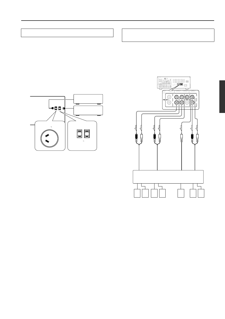
Connecting the power cords from other devices
AC OUTLETS
AC 120 V 60 Hz
SWITCHED
TOTAL 120W 1A MAX.
AC 230-240 V 50 Hz
SWITCHED 100W MAX.
AC OUTLET
Australian models
USA and Canadian
models
These jacks are for connecting an auxiliary power amplifier.
You can use an auxiliary power amplifiers to listen at louder
volumes than you can with the DTR-6.4 alone. When using a power
amplifier, connect each speaker to the power amplifier.
See page 17 for information regarding how to connect to a
subwoofer.
Note:
If you use a power amplifier connected to the SURR BACK PRE
OUT terminal and connect two surround back speakers to the
amplifier, set the “Hardware Config”
→ “b. Surr Back” setting to
“2ch (PRE OUT)” (see page 32).
Connecting the auxiliary power amplifier (DTR-
6.4 only)
INPUT 1
INPUT 2
OUTPUT
COMPONENT VIDEO
Y
IN
IN
IN
IN
FRONT
SURR
CENTER
SUB
WOOFER
VIDEO 2
VIDEO 1
VIDEO 2
DVD
MONITOR
OUT
DVD
TAPE
L
R
VIDEO 3
VIDEO 1
V
VIDEO 3
IN
IN
IN
OUT
IN
IN
OUT
OUT
OUT
OUT
OUT
S
FRONT
SPEAKERS
ZONE 2
SPEAKERS
SURROUND
SPEAKERS
CENTER
SPEAKER
R
L
R
L
ANTENNA
FM 75
AM
AC OUTLETS
CAUTION: SPEAKER IMPEDANCE
6 OHMS MIN. /SPEAKER
IN
RS232
IR
MODEL NO.
DTR-6.4
AV RECEIVER
AC INLET
AC 120 V 60 Hz
SWITCHED
TOTAL 120W 1A MAX.
IR OUT
56K
A
40K
B
ZONE 2
OUT
DC IN
24V 1A
L
R
ZONE 2
LINE OUT
ZONE 2
OPTICAL
1
2
OPTICAL
IN
OUT
SURROUND
BACK
SPEAKER
12 V
TRIGGER
OUT
A
B
REMOTE
CONTROL
IN
COAXIAL
IN
COAXIAL
DIGITAL
CD
L
R
GND
PHONO
FRONT
SURR
CENTER SURR BACK
(SB)
ZONE 2
SUB
WOOFER
PRE OUT
R
L
R
L
PR
PB
NCE
ER
SUR
BAC
SPE
FRONT
SURR
CENTER SURR BACK
(SB)
ZONE 2
SUB
WOOFER
R
L
R
L
5
2
1
4
3
7
6
1.
Front right speaker
2.
Front left speaker
3.
Surround right
speaker
4.
Surround left speaker
5.
Center speaker
6.
Surround back right
speaker
7.
Surround back left speaker
L (white)
R (red)
Power amplifier
R (red)
L (white)
L (white)
R (red)
Surr
ound
Fr
ont
Center
Surr
ound bac
k