Amplifier, Reference standard automotive – Infinity Kappa Series 3-Way Component System 1.1cs User Manual
Page 2
- 2 -
IMPORTANT: Installation of automotive stereo
components can require extensive experience
with a variety of mechanical and electrical proce-
dures. Although these instructions explain how to
install a Kappa Series 3-Way Component System
in a general sense, they do not show the exact
installation methods for your particular vehicle. If
you do not feel you have the experience, do not
attempt the installation yourself, but instead ask
your Authorized Infinity Car Audio Dealer about
professional installation options.
WARNING: Playing loud music in an automotive
environment can permanently damage your
hearing, as well as hinder your ability to hear
traffic. The maximum volume levels achievable
with Infinity speakers, combined with high
power amplification, may exceed safe levels for
extended listening. We recommend using low
volume levels when driving. Infinity accepts
no liability for hearing loss, bodily injury or
property damage as a result of use or misuse of
this product.
S
PEAKER
P
LACEMENT
Kappa speakers are designed to be easily
installed in stock speaker locations. While mount-
ing your speakers in the original factory locations
will, in most cases, provide excellent sonic
results, the best sounding installations are a
result of adherence to a few basic rules:
• For the most spacious stereo image, place the
left and right speakers as far apart as possible.
• For enhanced center image, place the left and
right speakers so they are equidistant from the
listening position. If possible, try to place them
as far forward as possible.
• For best treble response aim the tweeters
toward the listening position, and be sure there
are no obstructions between the tweeters and
the listener.
I
NSTALLATION
W
ARNINGS AND
T
IPS
• Always wear protective eyewear when using
any tools.
• Turn off all audio systems and other electrical
devices before you start. Disconnect the (–)
negative lead from your vehicle’s battery.
• Keep components in their package until final
installation. When moving a speaker, always
rest it with the cone or dome facing up. Never
use force to install any speaker.
• Check clearances on both sides of a planned
mounting surface before drilling any holes or
installing any screws. Remember that the
screws can extend behind the surface.
• At the installation sites, locate and make a note
of all fuel lines, hydraulic brake lines, vacuum
lines and electrical wiring. Use extreme caution
when cutting or drilling in and around these
areas.
CAUTION: In some cars, fuel tanks may be
located directly beneath the rear deck. Check
for adequate speaker basket clearance before
considering this location!
• Before drilling or cutting holes, use a utility
knife to remove unwanted fabric or vinyl, to
keep material from snagging in a drill bit or
saw.
• For door installations, check the clearance with
the windows throughout the range of the win-
dow’s travel, and verify that a mounted speaker
will not interfere with the window crank or
power window mechanism.
• If mounting components elsewhere, check for
clearance around rear deck torsion bars, glove
box or other structural elements.
• Do not mount components where they will get
wet.
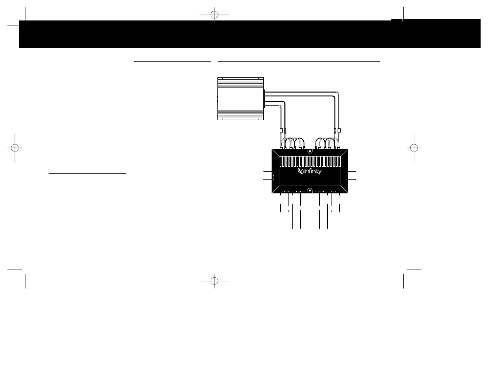
– +
MID
REFERENCE STANDARD AUTOMOTIVE
Component System Crossover Network
TO LEFT
MIDRANGE
TO LEFT
TWEETER
TO RIGHT
TWEETER
TO RIGHT
MIDRANGE
+
+
+
+
LO
HI
–
–
LO
HI
MID
HI
LO
MID
HI
LO
–
–
TO RIGHT
WOOFER
+
HI
LO
–
TO LEFT
WOOFER
+
HI
LO
–
FROM LEFT AMPLIFIERS
FROM RIGHT AMPLIFIERS
+
–
WOOFER
+
–
MIDRANGE
+
–
EMIT TWEETER
+
–
+
–
+
–
EMIT TWEETER
MIDRANGE
WOOFER
–
+
HI
To RIGHT
Woofer
–
HI
+
To LEFT
4" Midrange
– +
HI
–
To RIGHT
4" Midrange
To LEFT
Tweeter
–
To RIGHT
Tweeter
+
HI
+
MID
–
+
+
–
+
–
+
–
To LEFT
Woofer
GRN/WHT
GRN
GRN
LEFT
RIGHT
GRN/BLK
RED
BLK
BLK
RED
BLU
BLU/BLK
BLU
BLU/WHT
GRY/
BLK
GRY
GRY/
WHT
GRY
RED
RED/
BLK
RED
RED/
WHT
Connect Pigtail
Jumpers As Shown
Amplifier
W
IRE
C
ODES
Single Stereo Amplifier
Figure 1. This appli-
cation shows
connections for a
Kappa1cs system
and one stereo
amplifier.
Kappa 653.1cs OM 7/14/98 10:10 AM Page 2