Intel ESM-2743 User Manual
Page 37
User’s Manual
ESM-2740/2743 User’s Manual
37
2.4.7
Signal Description – ETX Connector X3 (ETXC)
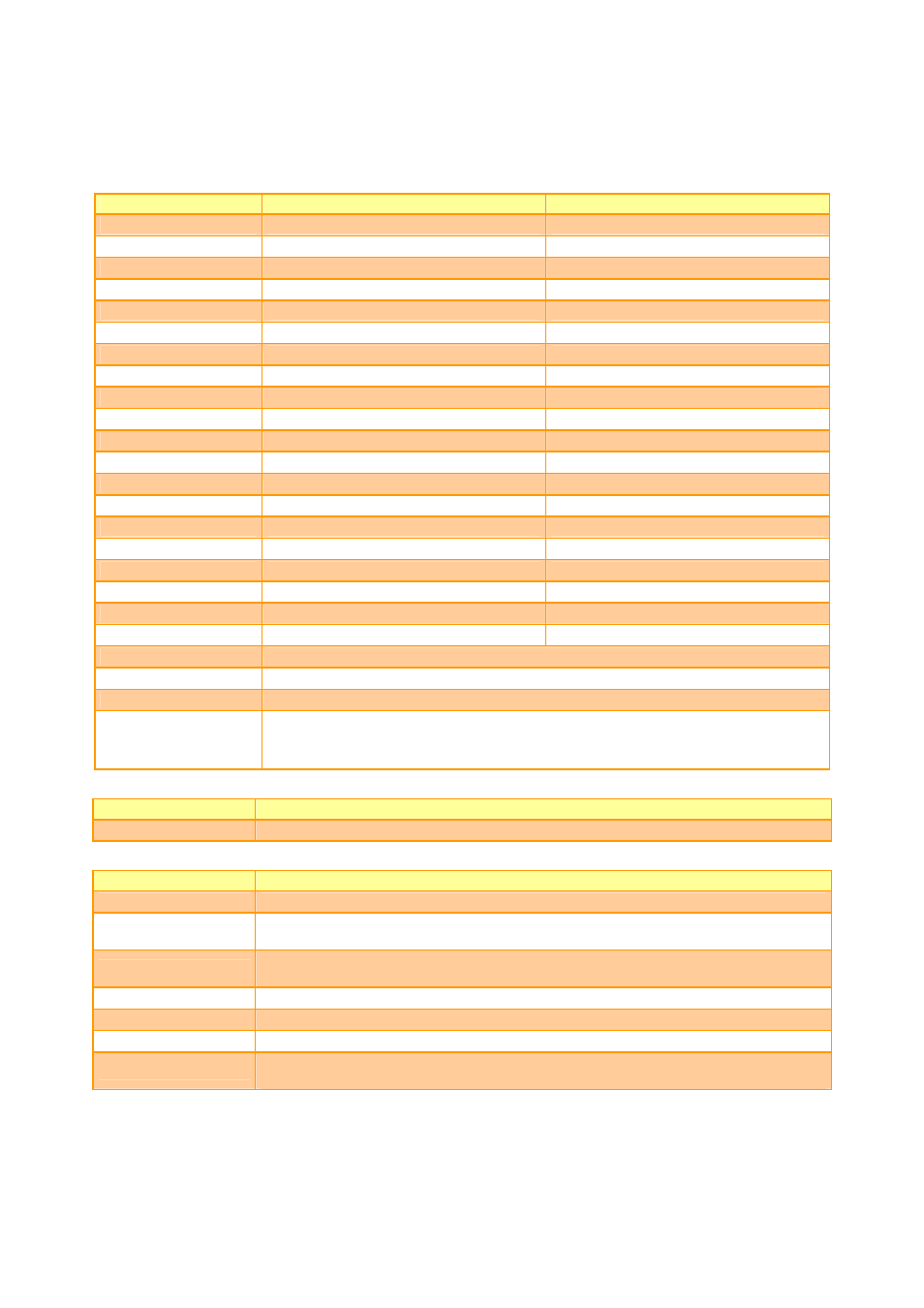
2.4.7.1 LVDS Flat Panel Interface Signals
Signal
1 Pixel / Clock LVDS Mode
2 Pixel / Clock LVDS Mode
LCDDO0
Txout0#
Odd Txout0#
LCDDO1 Txout0
Odd
Txout0
LCDDO2
Txout1#
Odd Txout1#
LCDDO3 Txout1
Odd
Txout1
LCDDO4
Txout2#
Odd Txout2#
LCDDO5 Txout2
Odd
Txout2
LCDDO6
Txclk#
Odd Txclk#
LCDDO7 Txclk
Odd
Txclk
LCDDO8
Txout3#
Odd Txout3#
LCDDO9 Txout3
Odd
Txout3
LCDDO10
-
Even Txout0#
LCDDO11 -
Even
Txout0
LCDDO12
-
Even Txout1#
LCDDO13 -
Even
Txout1
LCDDO14
-
Even Txout2#
LCDDO15 -
Even
Txout2
LCDDO16
-
Even Txclk#
LCDDO17 -
Even
Txclk
LCDDO18
-
Even Txout3#
LCDDO19 -
Even
Txout3
BIASON
Controls panel contrast voltage.
DIGON
Controls panel digital power.
ENBKL#
Controls backlight power enable.
I
2
C_DAT, I
2
C_CLK
I
2
C interface for panel parameter EEPROM. This EERPOM is mounted on the
LVDS receiver. The data in the EEPROM allows the EXT module to automatically
set the proper timing parameters for a specific LCD panel.
2.4.7.2 IrDA
(SIR)
Signals
Signal
Signal Description
IRTX, IRRX
Infrared transmit and receive pins.
2.4.7.3
Parallel Port Signals
Signal
Signal Description
STB#
This active-low signal is used to strobe the printer data into the printer.
AFD#
This active-low output tells the printer to automatically feed the next single line
after each preceding line has been printed.
PD[0:7]
This bi-directional parallel data bus is used to transfer information between the
CPU and the peripherals.
ERR#
This active-low signal indicates an error situation has occurred at the printer.
INIT#
This active-low signal is used to initiate the printer when low.
SLIN#
This active-low signal selects the printer.
ACK#
This active-low output from the printer indicates that it has received the previous
data and that it is ready to receive new data.