System board connector specifications, Monitor/signal, Parallel port – IBM Aptiva 2142 User Manual
Page 165
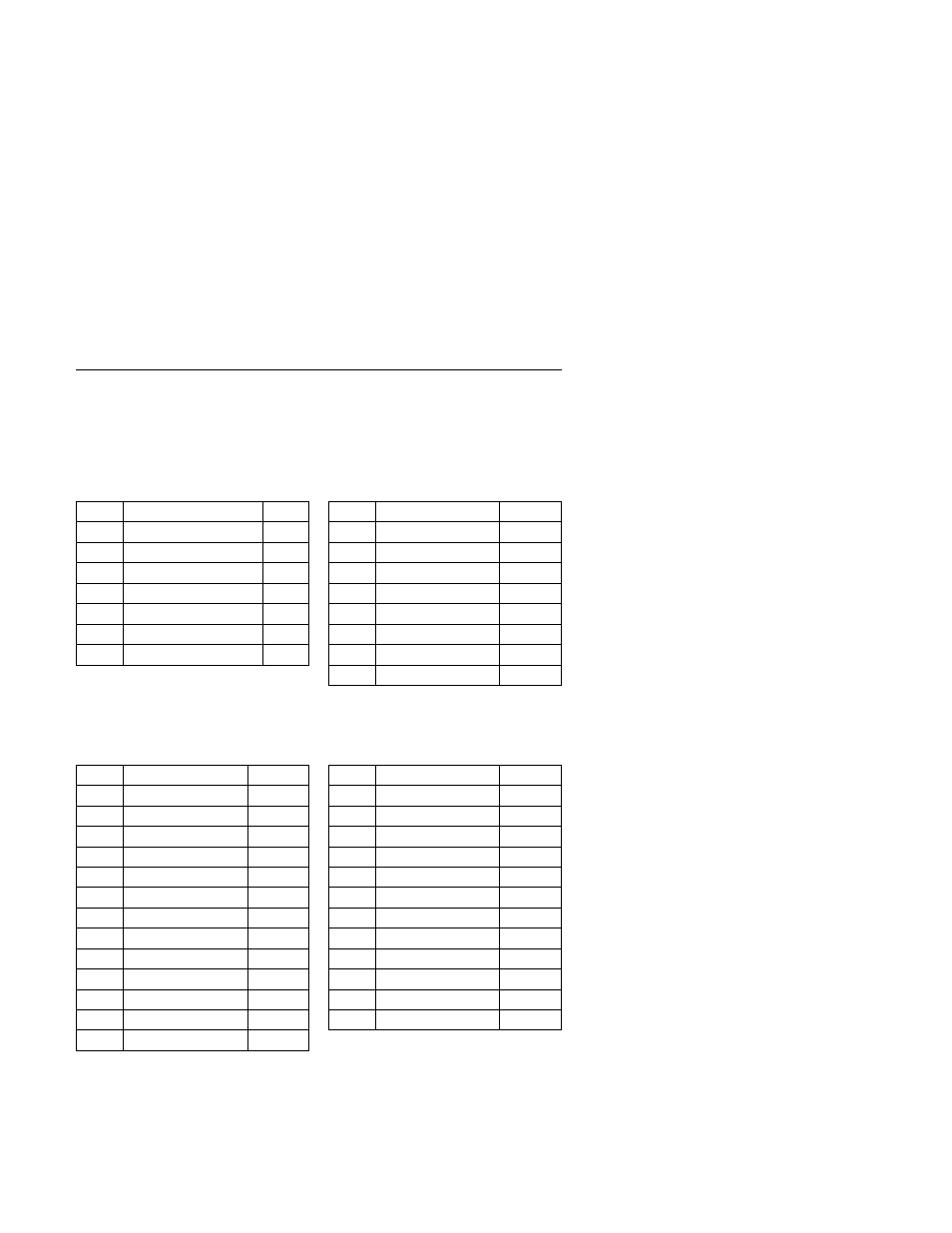
System Board Connector Specifications
Refer to “System Board Layout—Type A-1” on page 5-2 and “System Board
Layout—Type A-2” on page 5-5 for connector identification and location
information.
Monitor/Signal
Pin
Signal Name
I/O
Pin
Signal Name
I/O
1
Red Video
O
8
Blue Ground
2
Green Video
O
9
+5 V dc
3
Blue Video
O
10
Sync Ground
4
Monitor ID Bit 2
I
11
Monitor ID Bit 0
I
5
Sync Ground
12
SDA
I
6
Red Ground
13
Horizontal Sync
O
7
Green Ground
14
Vertical Sync
O
15
SCL
I
Parallel Port
Pin
Signal Name
I/O
Pin
Signal Name
I/O
1
Strobe
O
14
Auto Feed
N/A
2
Data Bit 0
I/O
15
Error
I
3
Data Bit 1
I/O
16
Initialize
O
4
Data Bit 2
I/O
17
Select (In)
O
5
Data Bit 3
I/O
18
Ground
Power
6
Data Bit 4
I/O
19
Ground
Power
7
Data Bit 5
I/O
20
Ground
Power
8
Data Bit 6
I/O
21
Ground
Power
9
Data Bit 7
I/O
22
Ground
Power
10
Acknowledge
I
23
Ground
Power
11
Busy
I
24
Ground
Power
12
Paper Empty
I
25
Ground
Power
13
Select
O
Parts/Test Point Locations
5-17