IDEAL INDUSTRIES CLASSIC HE18 User Manual
Page 40
40
classic HE
-
Installation & Servicing
SERVICING
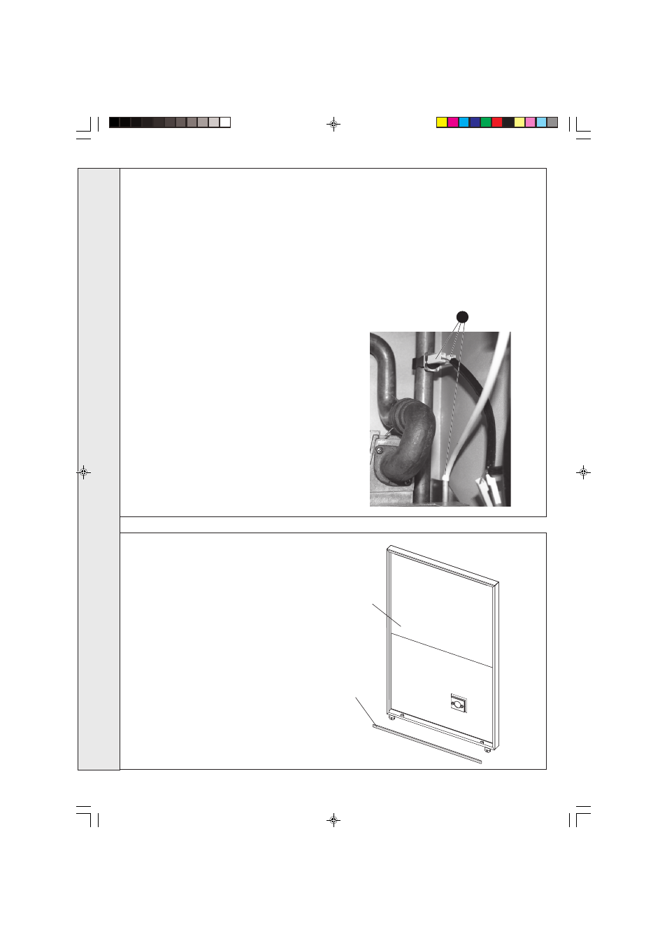
76 CASING FRONT SEAL REPLACEMENT
12. Remove the 2 rubber sealing grommets from the top
of the back panel to facilitate fitting the new assembly.
13. Fit the new heat exchanger assembly, complete with
water pipes, and hang it on the bottom key hole slots
and screws. Refit the top 2 screws and tighten 4
screws.
14. Replace the 2 rubber sealing grommets.
15. Reassemble in reverse order.
16. Remake all water connections, ensuring that the
compression fittings (if used) are correctly refitted.
17. Fully test all functions, including water and gas
soundness.
75 HEAT EXCHANGER REPLACEMENT
Note. Refer to Frame 7 (Boiler assembly - Exploded view) for illustration
of the procedure detailed below.
1. Refer to Frame 61.
2. Remove the burner / air box assembly. Refer to Frame 54.
3. Drain the system.
4. Disconnect the water connections. If compression fittings are used
then cut the pipes both above and below the fittings in order to
allow the heat exchanger assembly to be removed. Remove the
heat exchanger drain plug and drain the residual water into a
suitable receptacle.
5. Remove the fan/collector hood assembly, refer to Frame 55. Pull
off the electrical connections from the overheat thermostat and
pull off the white rubber tube from the siphon blockage sensing
pipe.
6. a. Rear Flue Outlet - Remove the two screws retaining the
recuperator top section. Pull the recuperator top section to
release the flue pipe connection.
b. Side Flue Outlet - Remove the 3 screws retaining the top
outlet connection casting and remove casting. Refer to Frame
26 No. 6.
7. Remove the combustion chamber by unscrewing the 4 tie rods.
8. Remove the thermostat sensors from the pockets on the heat
exchanger by removing the M3 screws and plates.
9. Remove the condensate sump. Refer to Frame 57.
10. Slacken 3 turns only the 2 bottom heat exchanger / interpanel
retaining screws and remove the top 2 heat exchanger/interpanel
retaining screws
11. Lift the heat exchanger / interpanel assembly upward and forward
to disengage key hole fixings. Pull the assembly downwards to
clear the water pipes from the back panel.
Note. Take care with any residual water held in the heat exchanger/
recuperator.
1. Refer to Frame 61.
2. Remove the old seal from the casing front and
thoroughly clean the casing surface.
3. Fit the new self adhesive seal.
4. Replace the boiler casing front.
Seal
Reverse of
casing panel
5
SER
VICING
201850-6.pmd
21/02/2008, 12:58
40