Cornelius WCF1411-A User Manual
Page 16
Continuous Flow Icemaker Service Manual
Publication Number: 630460324SER
- 12 -
© 2006, IMI Cornelius Inc.
M
OTOR
C
HECK
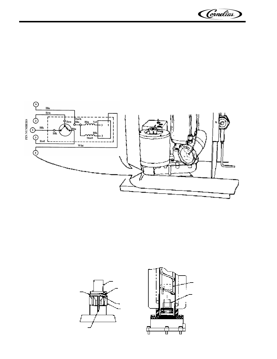
The resistance readings on the winding will be between 5 to 25 ohms. A meter capable of these low
readings must be used. The start relay cover must be removed.
If no continuity on start or run winding test, replace gearmotor. If continuity on grounded motor test,
replace gearmotor.
S
TART
R
ELAY
1.
Check between “2” and “4” on relay (with relay unplugged). If there is continuity replace the relay, as
the relay contacts should be open.
2.
Check between “3” and “4” on relay, if no continuity replace the relay.
FIGURE 6. GEARMOTOR ASSEMBLY
T
O
R
EPLACE
G
EARMOTOR
A
SSEMBLY
1.
Disconnect the icemaker from the electrical power source.
2.
Disconnect the transmission cable from the electrical box.
3.
Remove the 4 hex head bolts securing the evaporator to the top of the transmission.
4.
Remove the 4 bolt’s holding the transmission and bracket to frame base, while supporting the
weight of the evaporator. Remove the transmission from the unit.
5.
When replacing the transmission, it may be necessary to rotate the auger back and forth to align
the motor shaft and auger.
FIGURE 7. AUGER AND EXTRUDING HEAD REMOVAL
AUGER NUT
BEARING NYLON
GROOVE
EXTRUDING
HEAD
BEARING DELRIN
ANTI–ROTATION
RIB – 3 PLACES
AUGER
“D” DRIVE