Save these instructions, Symbols, Functional description – Makita HR5001C User Manual
Page 4
4
5.
Under normal operation, the tool is designed to
produce vibration. The screws can come loose
easily, causing a breakdown or accident. Check
tightness of screws carefully before operation.
6.
In cold weather or when the tool has not been
used for a long time, let the tool warm up for a
while by operating it under no load. This will
loosen up the lubrication. Without proper warm-
up, hammering operation is difficult.
7.
Always be sure you have a firm footing.
Be sure no one is below when using the tool in
high locations.
8.
Hold the tool firmly with both hands.
9.
Keep hands away from moving parts.
10. Do not leave the tool running. Operate the tool
only when hand-held.
11. Do not point the tool at any one in the area when
operating. The bit could fly out and injure some-
one seriously.
12. Do not touch the bit or parts close to the bit
immediately after operation; they may be
extremely hot and could burn your skin.
13. Some material contains chemicals which may be
toxic. Take caution to prevent dust inhalation
and skin contact. Follow material supplier safety
data.
SAVE THESE INSTRUCTIONS
WARNING:
MISUSE or failure to follow the safety
rules stated in this instruction manual
may cause serious personal injury.
SYMBOLS
USD202-2
The followings show the symbols used for tool.
V............................volts
A ...........................amperes
Hz..........................hertz
..................alternating current
.......................no load speed
.......................Class II Construction
.../min....................revolutions or reciprocation per
minute
..................number of blow
FUNCTIONAL DESCRIPTION
CAUTION:
•
Always be sure that the tool is switched off and
unplugged before adjusting or checking function on
the tool.
Switch action
CAUTION:
•
Before plugging in the tool, always check to see
that the switch trigger actuates properly and returns
to the “OFF” position when released.
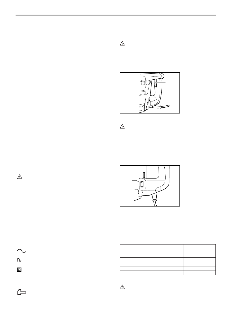
To start the tool, simply pull the switch trigger. Release
the switch trigger to stop.
Speed change
The revolutions and blows per minute can be adjusted
just by turning the adjusting dial. The dial is marked 1
(lowest speed) to 6 (full speed).
Refer to the table below for the relationship between the
number settings on the adjusting dial and the revolutions/
blows per minute.
CAUTION:
•
If the tool is operated continuously at low speeds for
a long time, the motor will get overloaded, resulting
in tool malfunction.
1. Switch trigger
1. Adjusting dial
1
003112
1
003119
Revolutions per minute
Number on adjusting dial
Blows per minute
6
240
2,150
5
230
2,050
4
200
1,800
3
170
1,500
2
130
1,200
1
120
1,100
006381