Miller Electric 250 User Manual
Page 40
.
A complete Parts List is available at www.MillerWelds.com
OM-217 455 Page 36
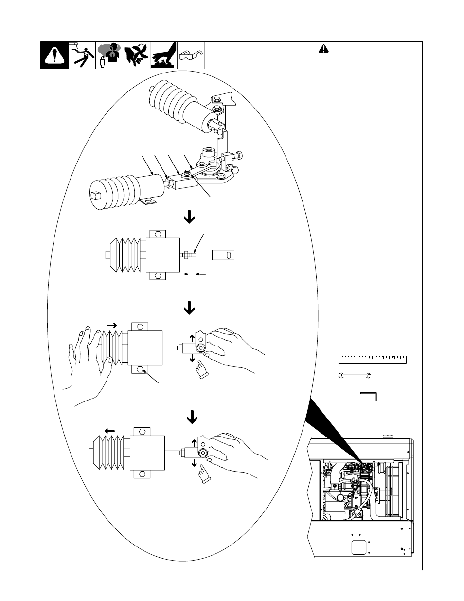
B. Checking Throttle Solenoid
Ref. 804 250-A / 802 649
!
Stop engine.
If the engine does not stay at idle
speed, verify the the throttle solenoid
and linkage is installed properly.
Adjusting Throttle Solenoid
1
Throttle Solenoid
2
Jam Nut
3
Solenoid Link
4
Shoulder Bolt
5
Throttle Lever
6
Solenoid Rod
7
Throttle Solenoid Mounting
Screw
Loosen jam nut, remove shoulder
bolt, and remove link from throttle le-
ver. Install link 5/8 in (16 mm) on so-
lenoid rod. Reconnect link to shoul-
der bolt and throttle lever.
Push solenoid rod into idle (ener-
gized) position and check for non-
binding lateral movement of throttle
link at throttle lever. If link binds, loos-
en solenoid mounting screws. Move
the solenoid slightly until the link
moves freely with solenoid in re-
laxed and energized positions.
Tighten screws.
Tighten jam nut.
Go to Step C.
3/8, 7/16 in
Tools Needed:
1
2
3
5/8 in
(16 mm)
5
6
7
Check for non-binding
movement of link with sole-
noid in energized position.
Check for non-binding
movement of link with
solenoid in relaxed
position.
4
5/32 in