Section 3 − definitions, Section 4 − specifications, 1. weld, power, and engine specifications – Miller Electric 250 User Manual
Page 16: 1. symbol definitions
.
A complete Parts List is available at www.MillerWelds.com
OM-217 455 Page 12
SECTION 3 − DEFINITIONS
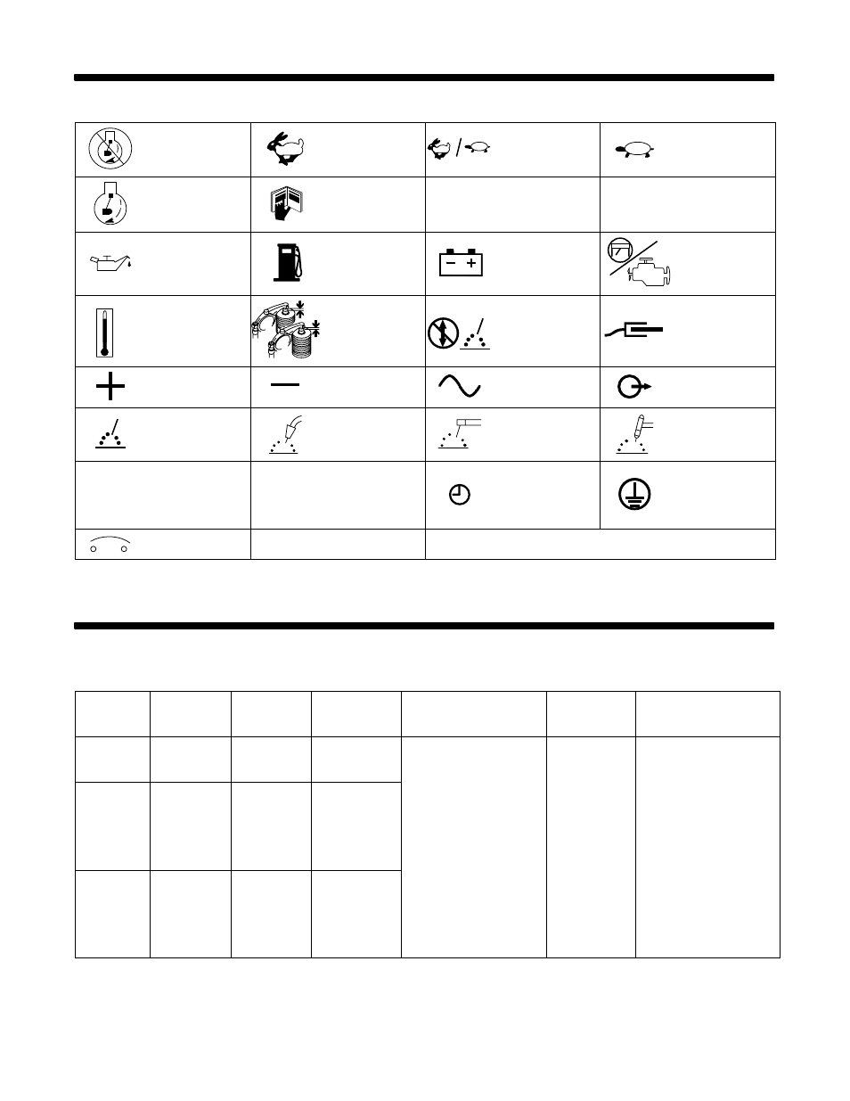
3-1. Symbol Definitions
Stop Engine
Fast
(Run, Weld/Power)
Fast/Slow
(Run/Idle)
Slow (Idle)
Start Engine
Read Operator’s
Manual
A
Amperes
V
Volts
Engine Oil
Fuel
Battery (Engine)
Engine
Temperature
Check Valve
Clearance
Do not switch while
welding
Work Connection
Positive
Negative
Alternating Current
(AC)
Output
Welding Arc
(Electrode)
MIG (GMAW),
Wire
Stick (SMAW)
TIG (GTAW)
h
Hours
s
Seconds
Time
Protective Earth
(Ground)
Circuit Protector
SECTION 4 − SPECIFICATIONS
4-1. Weld, Power, and Engine Specifications
.
Also see Performance Data in Section 13.
Welding
Mode
Weld Output
Range
Rated
Welding
Output
Maximum
Open Circuit
Voltage
Generator Power Rating
Fuel
Capacity
Engine
CC/AC
40 − 250 A
250 A, 25 V,
100% Duty
Cycle
80
CC/DC
40 − 250 A
250 A, 25 V,
100% Duty
Cycle
72
Peak: 10.5 kVA/kW
Continuous: 9.5 kVA/kW,
Single-Phase,
84/42 A, 120/240 V AC,
60 Hz
(while not welding)
12 gal
(45 L) Tank
Kubota D722
Water-Cooled,
Three-Cylinder
Four-Cycle
18.8 HP
Diesel Engine
CV/DC
17 − 28 V
275 A, 25 V,
60% Duty
Cycle
250 A, 28 V,
100% Duty
Cycle
41
g