Rear panel, Mic input, Line input – MACKIE Onyx 80 User Manual
Page 21: Insert, Owner ’s manual, Owner’s manual
21
Owner’s Manual
Owner
’s Manual
RISK OF ELECTRIC SHOCK
DO NOT OPEN
REPLACE WITH THE SAME TYPE FUSE AND RATING.
DISCONNECT SUPPLY CORD BEFORE CHANGING FUSE
UTILISE UN FUSIBLE DE RECHANGE DE MÊME TYPE.
DEBRANCHER AVANT DE REMPLACER LE FUSIBLE
WARNING:
TO REDUCE THE RISK OF FIRE OR ELECTRIC SHOCK, DO NOT
EXPOSE THIS EQUIPMENT TO RAIN OR MOISTURE. DO NOT REMOVE COVER.
NO USER SERVICEABLE PARTS INSIDE. REFER SERVICING TO QUALIFIED PERSONNEL.
CAUTION
AVIS:
RISQUE DE CHOC ELECTRIQUE — NE PAS OUVRIR
SERIAL NUMBER
MANUFACTURING DATE
1
LINE
MIC
INSERT
(BALANCED)
DIRECT OUTS
CHAN 1-8
ON
YX MIC PRE
2
LINE
MIC
INSERT
ON
YX MIC PRE
3
LINE
MIC
INSERT
ON
YX MIC PRE
4
LINE
MIC
INSERT
ON
YX MIC PRE
5
LINE
MIC
INSERT
ON
YX MIC PRE
6
LINE
MIC
INSERT
ON
YX MIC PRE
7
LINE
MIC
INSERT
ON
YX MIC PRE
8
LINE
MIC
INSERT
ON
YX MIC PRE
Rear Panel
This is where all the connections are made to the
Onyx 80 Series (except the headphones and lamps).
67. MIC Input
This is a female XLR connector, which accepts a bal-
anced microphone input from almost any type of micro-
phone. The microphone preamps feature our new Onyx
design, with higher fi delity and headroom rivaling any
standalone mic preamp on the market today.
The XLR inputs are wired as follows:
Pin 1 = Shield or ground
Pin 2 = Positive (+ or hot)
Pin 3 = Negative (– or cold)
68. LINE Input
This is a 1/4" TRS connector, which accepts a balanced or
unbalanced line-level input signal from almost any source.
When connecting a balanced signal to the LINE inputs,
wire them as follows:
Tip = Positive (+ or hot)
Ring = Negative (– or cold)
Sleeve = Shield or ground
When connecting an unbalanced signal, wire them as
follows:
Tip = Positive (+ or hot)
Sleeve = Shield or ground
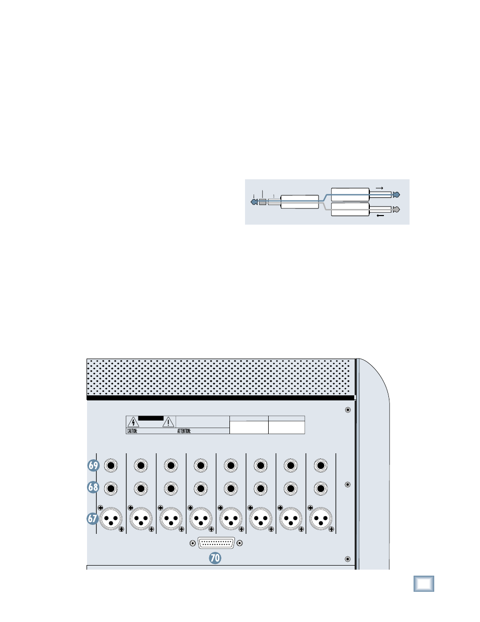
69. INSERT
These 1/4" TRS jacks provide a send and return point
for each channel. Use the INSERT jacks to connect
serial effects devices such as compressors, equalizers,
de-essers, or fi lters to each individual channel.
The INSERT points are after the GAIN, Polarity, and
Low Cut controls, but before the EQ and Fader controls.
The send (tip) is low-impedance, capable of driving any
device. The return (ring) is high-impedance and can be
driven by almost any device.
Special insert cables are available, specially designed
for this kind of insert jack. They are wired as follows:
“from tip”
this plug connects to one of the
mixer’s Channel Insert jacks.
“to ring”
tip
ring
sleeve
SEND to processor
RETURN from processor
(TRS plug)
Tip = Send (output to effects device)
Ring = Return ( input from effects device)
Sleeve = Common ground (connect shield to all
three
sleeves)
Besides being used for inserting external devices,
these jacks can also be used as channel direct outputs;
post-GAIN, post-LOW CUT, and pre-EQ. This is an unbal-
anced direct out, in contrast to the DIRECT OUTS on
the rear panel, which are balanced direct outputs, post-
GAIN, post-INSERT, and pre-EQ.