Figure 44 - fuse/circuit breaker locations – Middleby Marshall PS200 series User Manual
Page 77
76
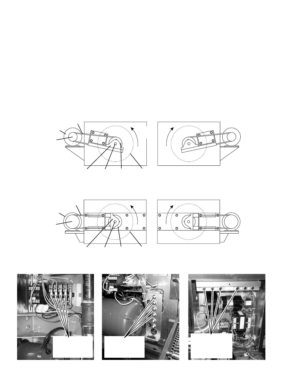
A. PS555/570-series ovens
All PS555/570-series ovens are equipped with two 1hp blower
motors. Each motor indirectly drives a pulley on the shaft
of a blower wheel with a fan belt.
Two main designs exist for the PS555/570 blower fan sys-
tem:
PS570/570S design. In this version, the pillow block
bearings for the blower wheel shaft were mounted up-
right, on brackets that were parallel to the fan belts.
See Figure 42.
PS555/570G design. In this version, the pillow block
bearings are mounted with the grease fittings pointing
in towards the center of the oven. See Figure 43.
Figure 44 - Fuse/circuit breaker locations
PS570/570S:
15A fuses located on
left side of machinery
compartment
PS555 (early):
15A breakers located
inside left blower
motor compartment
PS555 (current),
PS570G: 15A
breakers located on
right side of machinery
compartment
The two designs share many common parts, including blower
wheels, motors, and bearings. From a service standpoint,
the major difference is the size of the pulleys and the length
of the belts.
Blower motors on all PS555/570-series ovens are rated for
208-240V, single-phase, and are protected by:
A built-in thermal overload protection device.
Two 15A fuses or 15A circuit breakers. Refer to Figure
44 for the location of the fuses/breakers.
In addition, each blower fan is protected by an air pressure
saftety switch that prevents the burner/heating elements
from activating if the fan is not rotating. See Air Pressure
Safety Switch on Page 81.
Figure 42 - PS570/570S blower configuration
Figure 43 - PS555/570G blower configuration
Bearing
Pulley
Blower
shaft
Blower
motor
Pulley
Belt
Blower wheel
(inside oven)
Direction
of rotation
Bearing
Pulley
Blower
shaft
Blower
motor
Pulley
Belt
Blower wheel
(inside oven)
SECTION 3 - SERVICING COMPONENTS