Miller Electric 652 User Manual
Page 29
OM-228 470 Page 25
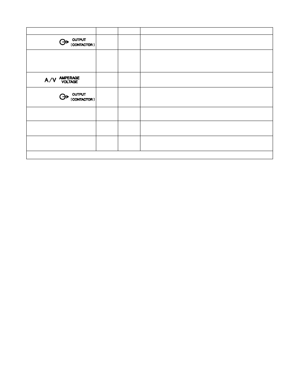
4-13. Remote 14 Receptacle RC8 And Terminal Strip 1T Information
Socket
Terminal
Information
24 VOLTS AC
A
A
24 volts ac. Protected by supplementary protector CB2.
24 VOLTS AC
B
B
Contact closure to A completes 24 volts ac contactor control circuit.
C
C
Command reference; 0 to +10 volts dc (CC), +10 volts dc (CV).
REMOTE OUTPUT CONTROL
D
D
Remote control circuit common.
E
E
0 to +10 volts dc input command signal from remote control.
F
*
Current feedback; 1 volt per 100 amperes.
H
*
Voltage feedback; 1 volt per 10 arc volts.
115 VOLTS AC
I
I
115 volts, 15 amperes, 60 Hz ac. Protected by supplementary protector
CB1.
115 VOLTS AC
J
J
Contact closure to I completes 115 volts ac contactor control circuit.
GND
K
G
K
*
Chassis common.
Circuit common for 24 and 115 volts ac circuits.
REMOTE POWER ON/OFF
*
L
To remote On/Off switch
REMOTE POWER ON/OFF
*
M
To remote On/Off switch.
REMOTE VOLTAGE SENSING
N
N
Voltage sensing signal from Negative (−) weld output terminal.
REMOTE VOLTAGE SENSING
*
P
Voltage sensing signal from Positive (+) weld output terminal.
* Not Used