6. symbols and definitions, Section 4 − installation, 1. specifications – Miller Electric 652 User Manual
Page 18
OM-228 470 Page 14
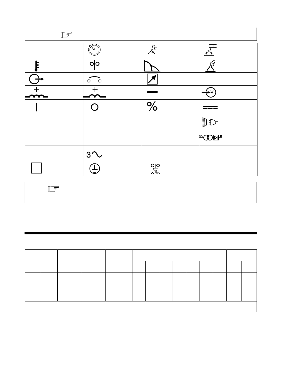
3-6. Symbols And Definitions
Some symbols are found only on CE products.
NOTE
A
Amperes
Amperage/Voltage
Control−Panel
Gas Tungsten Arc
Welding (GTAW)
Shielded Metal Arc
Welding (SMAW)
Temperature
Wire Feeder
Arc Force (DIG)
Gas Metal Arc
Welding (GMAW)
Output
Circuit Breaker
Remote
V
Volts
Positive High In-
ductance Weld
Output Terminal
Positive Low In-
ductance Weld
Output Terminal
Negative Weld
Output Terminal
Input
On
Off
Percent
Direct Current
U
0
Rated No Load
Voltage (Average)
U
1
Primary Voltage
U
2
Conventional Load
Voltage
Line Connection
I
1
Primary Current
I
2
Rated Welding
Current
X
Duty Cycle
Three-Phase
Transformer
Rectifier
IP
Degree Of
Protection
Three-Phase
S
1
KVA
Hz
Hertz
S
Suitable For Areas
Of Increased
Shock Hazard
Protective Earth
(Ground)
Submerged Arc
Welding (SAW)
The terms Sub Arc and Submerged Arc mean the same thing, and are used interchangeably
throughout this manual.
Note
SECTION 4 − INSTALLATION
4-1. Specifications
Model
IP
Rated
Welding
Amperage/
Voltage
Max
Amperes Input at Rated Load Output,
50 or 60 Hz, Three-Phase
Model
IP
Rating
Welding
Output
Voltage
Range DC
Max
OCV−DC
230
V
380
V
400
V
440
V
460
V
520
V
575
V
KVA
KW
650
21M
650 A @ 44
Volts DC,
50 − 815 A
In CC Mode
72 (70) VDC
In
CC Mode
126
3.8*
77
1.9*
73
1.8*
66
1.6*
63
1.9*
54
1.1*
50.4
1.4*
50
1.52*
34.8
0.76*
650
Amp
21M
Volts DC,
100% Duty
Cycle
10 − 65 V In
CV Mode
70 (66) VDC
In
CV Mode
3.8*
1.9*
1.8*
1.6*
1.9*
1.1*
1.4*
1.52*
0.76*
*While idling
( ) Indicates specification differences for CE models