Mldv series gas fireplace, Fp1953 rigid pipe, Venting installation – Monessen Hearth DIRECT VENT MLDV500 User Manual
Page 16: Rear wall vent installation (5" x 8" venting only), Fp1954 wall framing
16
75D0004
MLDV Series Gas Fireplace
•
Only one 45 degree elbow is allowed in these installations.
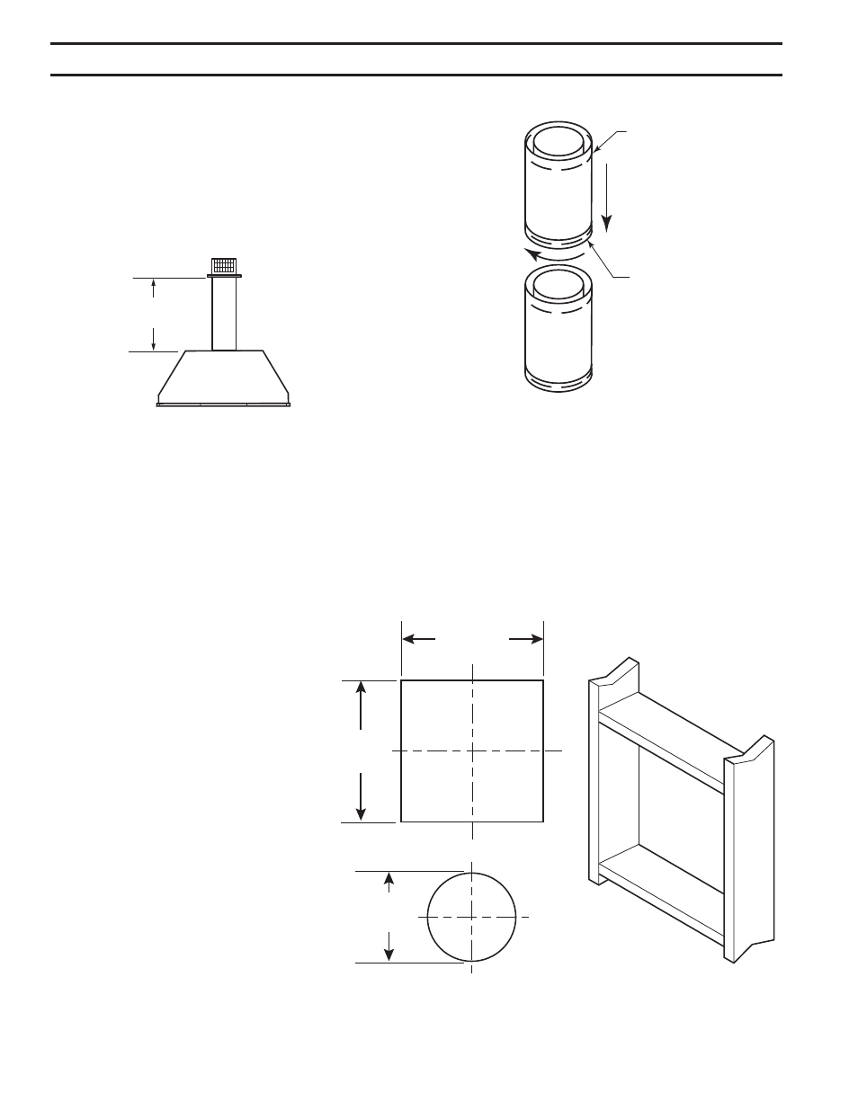
1. Rigid vent pipes and fittings have special twist-lock connections. Assemble the desired
combination of pipe and elbows to the appliance adapter.
Twist-Lock Procedure: The female ends of the pipes and fittings have three (3) locking
lugs (indentations). These lugs will slide straight into matching slots on the male end of
adjacent pipes and fittings. Push the pipe sections together and twist one section clockwise
approximately one-quarter turn until the sections are fully locked. Figure 15
. Refer to venting and termination instructions for further instructions.
3. Locate and cut the vent opening in the
wall. For combustible walls first frame in
opening.
Combustible Interior Walls: Cut a 1
1
/
"
x 10
1
/
" hole through the interior wall.
Combustible Exterior Walls: Cut a 10
1
/
"
x 10
1
/
" square hole through the exterior
wall frame. Figure 16
Noncombustible Walls: Hole opening
should be 8
1
/
" (16 mm) in diameter.
4. The center of the hole should align with
the center line of the horizontal rigid vent
pipe end. Allow 1/4" minimum rise per foot.
Figure 16
5. Apply a bead of non-hardening mastic
around the outside edge of vent cap. Posi-
tion the vent cap in the center of hole on the
exterior wall with the word "UP" on the vent
cap facing up. Insure proper clearance of
1" to combustibles is maintained. Attach
the vent cap with four (4) wood screws
supplied. Figure 17
VENTING INSTALLATION
FP1953
rigid pipe
Female Locking
Lugs
Male Slots
NOTE: Horizontal runs of
vent must be supported every
three feet (914 mm). Use wall
straps for this purpose.
Figure 15 -
Rigid Vent Pipe Connections
REAR WALL VENT INSTALLATION (5" x 8" VENTING
ONLY)
When installed as a rear vent unit, this appliance may be vented directly to
a termination located on the rear wall behind the appliance. Only an MHSC
brand termination is allowed for this application.
•
The maximum horizontal distance between the rear of the appliance
and the termination is 0" (508 mm). Figure 14
DVR584-600
Rear vent no elbows
2/99 djt
Maximum
0"
Top View Flat Installation
Figure 14 - Rear Vent Application,
Maximum Horizontal Distance
FP1954
wall framing
10
1
/
"
(67 mm)
10
1
/
"
(67 mm)
8
1
/
"
(16 mm)
Figure 16 -
Exterior Wall Framing Dimensions
Combustible Wall
Noncombustible
Wall
FP1954