Remote wall switch installation, Warning, Remote wall mounted switch – Monessen Hearth Direct Vent Gas Fireplace KHLDV SERIES User Manual
Page 26: Optional fan/blower system
26
73D0024
ON
OFF
OPTIONAL REMOTE
WALL SWITCH
ON
OFF
OPTIONAL REMOTE
WALL SWITCH
PILOT
HI
LO
ON
OFF
TH
TP
TH/TP
ON
OFF
RS
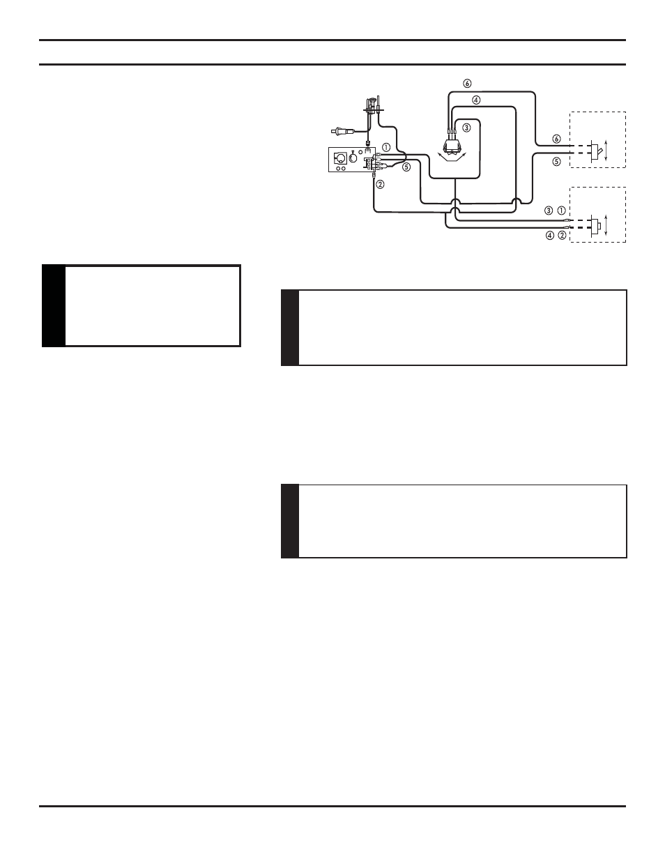
REMOTE WALL MOUNTED SWITCH
A remote wall switch and up to fifteen (15) feet of 18 Ga.
wire may be used with this appliance. Attach the wall
switch in a junction box at the desired location on the wall.
See Figure 26. Do not extend beyond the wall switch wire
length provided.
NOTE: Extended lengths of wire may cause the
fi replace not to function properly. Longer length of
wire is permitted if the wire is made out of larger
gauge (diameter) wire. Always check with local
code.
Figure 26 - Wiring Diagram for Wall Switch
REMOTE WALL SWITCH INSTALLATION
Do not connect wall
switch of heater to a
110V circuit.
W
ARNING
OPTIONAL FAN/BLOWER SYSTEM
IMPORTANT: Always check local building codes. This installation must comply with local regulations
as well as the National Electric Code.
WIRING
1. Before installing the blower, wire the receptacle into an electrical circuit. This should be done before framing the fire-
place. Wire with minimum 60ºC wire in accordance with prevailing codes.
2. Remove the external junction box cover by removing the screw from the right side of the outside firebox wall. Junction
box was installed at the factory.
3. The junction box cover has a factory installed
“romex” style strain relief connector. After
connecting the wires, route the wire leads
through this connector. Refer to the wiring
diagram in Figure 27a.
BEFORE INSTALLING BLOWER
1. Always turn off the gas supply and allow the unit to cool down before proceeding.
2. Clean the inside of the firebox (wall and floor), where the blower and wires will be installed. Make sure the firebox
wall and floor are clean and dry before mounting the blower.
NOTE: It is very important to arrange the blower wires and wire assembly so that wires do not come in contact with
blower blades or firebox.
INSTALLING BLOWERS
1. Remove screen rod assemblies by lifting rod and pushing back and down to release rod from the three hooks located
behind the face of the fireplace on the right, left, and middle.
2. Remove the plate located in front of the glass at the bottom.
3. Rotate the access doors on the right and left side of the glass toward the glass.
4. Remove glass frame by releasing the three latches located at the top of the firebox. Tilt glass away from the unit, lift
glass frame up and away from the unit. See Fig. 32.
5. Remove
logs.
6. Remove hearth brick, wall brick and rear brick. NOTE: Remove brackets that secure wall brick.
Before installing the blower, turn off the fi replace and allow to cool.
Only a qualifi ed service person should service and repair the fi re-
place. A qualifi ed service person should connect and disconnect
the fi replace to gas supply. Follow all local codes.
W
A
RNING
Electrical connections should only be performed by a qualifi ed,
licensed electrician. Main power supply must be turned off before
connecting fans to the main electrical power supply or performing
service.
CA
U
T
IO
N