Dca-400ssv— troubleshooting (diagnostic lamp) – Multiquip 60 Hz Generator DCA-400SSV User Manual
Page 54
PAGE 54 — DCA-400SSV— OPERATION AND PARTS MANUAL — REV. #0 (04/19/06)
DCA-400SSV— TROUBLESHOOTING (DIAGNOSTIC LAMP)
The engine controller of this generator diagnoses problems
that arise from the engine control system and the engine
itself. The malfunction can be determined by examining the
flashing pattern of the diagnostic lamp (Figure 69) located in
the control box.
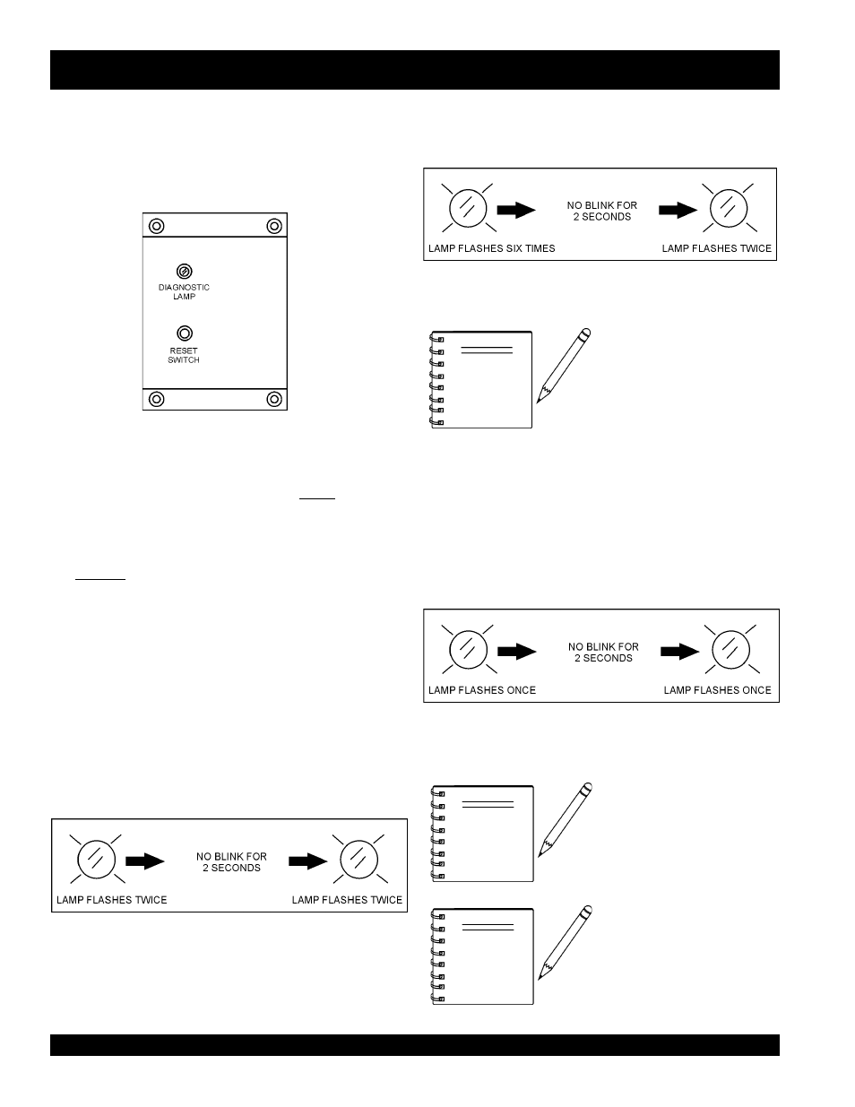
Figure 69. Diagnostic Panel
Method of Operation
1. Normally, the diagnostic lamp will be
dimly lit when the
MPEC Control Switch is placed in the MANUAL
position.
2. If engine trouble occurs, the diagnostic lamp will be
brightly lit as long as the control switch is left in the
manual position.
3. The diagnostic lamp will indicate an error code via a
flashing pattern on the lamp. This pattern will become
visible once the the reset button on the control box has
been pushed and released. The error code consists of a
series of flashes by the lamp. The error codes are defined
as follows:
Example Error Code 1.
Figure 70 displays the error code for
low radiator coolant.
Figure 70. Error Code Low Radiator Coolant
Example Error Code 2.
Figure 71 displays the error code for
high temp intake.
Figure 71. Error Code High Temperature Intake
The error code will flash each
time the reset button is pressed
and released until the problems
have been corrected.
NOTE
4. In a situation where several engine malfunctions occur
simultaneously, the code for each malfunction will flash
one after another in sucession.
5. After all engine related malfunctions have been diagnosed
and corrected, and the generator is operating in a normal
maner the following code (Figure 72) should be displayed
once the reset button is pressed and released
Figure 72. Normal Operating Code
For a complete understanding of
error codes and troubleshooting
procedures, refer to the enclosed
engine instruction manual.
NOTE
When the
MPEC Control
Switch is placed in the AUTO
position, the same error codes
will apply. Codes will not be
active until the unit is activated.
NOTE