Rear panel features, Ac input receptacle, Power switch – MACKIE QUAD EQ User Manual
Page 9: Measurement microphone input, Channel trs inputs, Channel xlr inputs, Channel trs outputs, Channel xlr outputs, Quad eq, Owner’ s manual
8
QUAD EQ
Quad EQ
9
Owner’s Manual
Owner’
s Manual
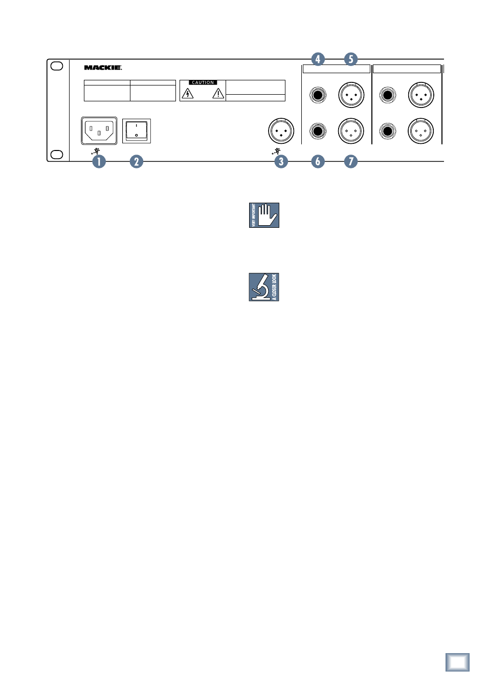
Rear Panel Features
1. AC Input receptacle
This is a standard 3-prong IEC power connector. Con-
nect the detachable linecord (included in the box with
your Quad EQ) to this power receptacle, and plug the
other end of the linecord into an AC outlet.
The Quad EQ has a universal power supply that can
accept any AC voltage from 100 VAC to 240 VAC.
It will work virtually anywhere in the world, includ-
ing Walton-on-the-Naze, England. That’s why we call it
a “Planet-Earth” power supply! The power supply is less
susceptible to voltage sags or spikes than conventional
supplies, providing greater electromagnetic isolation
and better protection against AC line noise.
2. Power switch
Press the top edge of this rocker switch in to turn on
the Quad EQ.
Turn it off by pressing the bottom edge of the rocker
switch. Audio will still pass through even when the Quad
EQ is turned off.
3. Measurement Microphone input
This XLR-male jack is used to connect the supplied
RA-420 measurement microphone.
The microphone preamplifier circuit has been opti-
mised to work with the supplied microphone: it has a
fixed gain setting, and 48 V phantom power is applied at
all times.
When the front panel MIC button is engaged, the
microphone signals from the measurement microphone
will enter the Quad EQ for real time analysis, and the
other inputs are disconnected and will not play through
the Quad EQ.
Rear Panel Ins and Outs (channels A-D)
The IN and OUT jacks will pass through
signals if the power is not applied to the
Quad EQ. For example, if your mixer’s left
main output is coming into the Quad EQ channel-A in-
put, and the Quad EQ is off, the same signal will appear
at the channel-A output jack.
These inputs and outputs are line-level,
and you would normally connect them to a
mixer or line-level component in your sys-
tem. Do not connect microphones or instru-
ments directly to the inputs.
4. TRS Inputs and 5. XLR Inputs
These 1/4" TRS (tip-ring-sleeve) jacks are the inputs
for the channels. They can accept balanced TRS plugs,
or unbalanced 1/4" TS (tip-sleeve) plugs, tip hot.
The female XLR jacks are also the inputs for the chan-
nels (pin 2 hot, pin 3 cold, pin 1 shield).
For each channel, the XLR and TRS inputs are in
parallel, so you can choose either style as an input. You
can use unbalanced TS connections, but we recommend
using balanced connections wherever possible.
6. TRS outputs and 7. XLR Outputs
These 1/4" TRS jacks are the outputs for the channels.
They can accept balanced TRS plugs, or unbalanced
1/4" TS plugs, tip hot.
The male XLR jacks are also the outputs for the chan-
nels.
For each channel, the balanced XLR and TRS outputs
are in parallel, so you can choose either style of output.
Both TRS and XLR outputs can be used simultaneously.
�����������
���
�������
�������������
������������������
�������
��������������
�����������
�������������������������������������������
�������������������������������������������
���������
�����������������������������������������������������
����������������������������������������������������������������
�������������������������������������������������������������������������
�����
������������������������������������������
��������
���
��
��
���
���
��
��
���
���
��
��
���
���
��
��
���
����������������������������������������������������������������������������������������������������������
�����������������������������������������������������������������������������������������������
�����
������������������������
�
�
�
�