MaxTech FHX-1200 User Manual
Page 5
3
IN
OUT
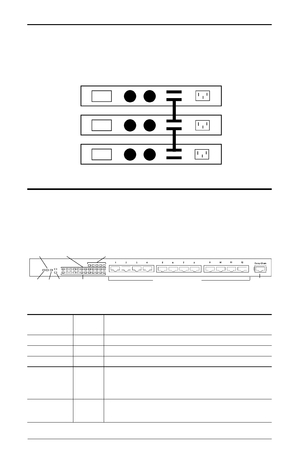
Figure 4 Stacking hubs
Connect the supplied stacking cable to the OUT port of the first hub and connect the
cable to the IN port of the second hub (refer to Figure 4).
Do not connect an OUT port
to an OUT port or an IN port to an IN port.
Section 3 - LED indicators
The front-panel LEDs (see Figure 5) show the status of the hub and the network
connections.
LED
Function
POWER
On
Hub is powered on
Off
Hub is powered off
COLLISION
Amber
Data Collision has occurred
FX/ON
Green
100 Base-FX module is installed and ON
UTILIZATION
Green
Indicates bandwidth being used
PARTITION
Off
Port is operating normally
(1 - 12, FX)
Flash
Data error has occurred
On
The port has been disconnected from the network due to exces-
sive collisions caused by the attached computer
LINK/ACTIVITY
On
A network link is established
(1 - 12, FX)
Blink
Data is being transmitted
RJ-45 CONNECTORS
DAISY-
CHAIN
LINK/ACTIVITY (12)
COL
PWR FX/ON FX
ERROR (12)
UTILIZATION (5)
Figure 5 Hub LEDs
IN
OUT
IN
OUT