Save these instructions, Symbols, Functional description – Makita 3710 User Manual
Page 4
4
10. Be careful of the bit rotating direction and the
feed direction.
11. Do not leave the tool running. Operate the tool
only when hand-held.
12. Always switch off and wait for the bit to come to
a complete stop before removing the tool from
workpiece.
13. Do not touch the bit immediately after operation;
it may be extremely hot and could burn your
skin.
14. Always lead the power supply cord away from
the tool towards the rear.
15. Do not smear the tool base carelessly with thin-
ner, gasoline, oil or the like. They may cause
cracks in the tool base.
16. Draw attention to the need to use cutters of the
correct shank diameter and suitable for the
speed of the tool.
17. Some material contains chemicals which may be
toxic. Take caution to prevent working dust inha-
lation and skin contact. Follow material supplier
safety data.
SAVE THESE INSTRUCTIONS
WARNING:
MISUSE or failure to follow the safety
rules stated in this instruction manual
may cause serious personal injury.
SYMBOLS
USD201-2
The followings show the symbols used for tool.
V............................volts
A ...........................amperes
Hz..........................hertz
..................alternating current
.......................no load speed
.......................Class II Construction
.../min ....................revolutions or reciprocation per
minute
FUNCTIONAL DESCRIPTION
CAUTION:
•
Always be sure that the tool is switched off and
unplugged before adjusting or checking function on
the tool.
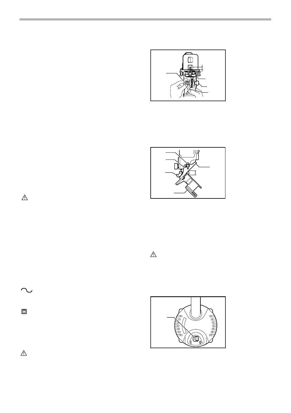
Adjusting bit protrusion
To adjust the bit protrusion, loosen the clamping nut and
move the tool base up or down as desired by turning the
adjusting screw. After adjusting, tighten the clamping nut
firmly to secure the tool base.
Adjusting angle of tool base
Loosen the wing bolts and adjust the angle of the tool
base (5° per graduation) to obtain the desired cutting
angle.
Adjusting amount of chamfering
To adjust the amount of chamfering, loosen the wing nuts
and adjust the trimmer shoe.
CAUTION:
•
With the tool unplugged and switch in the “OFF”
position, rotate the collet nut on the tool several
times to be sure that the bit turns freely and does
not contact the base or trimmer shoe in any way.
Switch action
To start the tool, move the switch lever to the I (ON) posi-
tion. To stop the tool, move the switch lever to the O
(OFF) position.
n
˚
1. Bit protrusion
2. Base
3. Clamping nut
4. Scale
5. Adjusting screw
1. Wing bolt
2. Graduation
3. Wing nut
4. Trimmer shoe
5. Amount of
chamfering
6. Base
1. Switch lever
1
2
3
4
5
006631
1
2
3
4
5
6
006632
1
006614