MPI Technologies FCX User Manual
Page 10
,167$//$7,21
7\SLFDO LQVWDOODWLRQ H[DPSOHV
The flue/combustion air system piping may be either
horizontal or vertical or a combination of both, ob-
serving the following:
• The maximum unrestricted horizontal or verti-
cal flue length shall not be more than 16.4 ft
(5 m).
• For each 90-degree elbow used in the flue sys-
tem, subtract 3.3 ft (1m) from the total allowa-
ble length.
• For each 45-degree elbow used in the flue sys-
tem, subtract 1.65 ft (0.5m) from the total allo-
wable length.
• Horizontal runs of the flue system must pitch
down 3/4 inch per yard (2 cm per m) of length
towards the boiler to facilitate proper flue pro-
ducts condensate drainage.
• Termination of a horizontal flue system shall
not be less than 5.96 ft(1.8m) above ground
unless other provisions are made to minimize
the likelihood of flue/combustion air intake
blockage.
• Do not place the flue terminal less than 3.3 ft.
(1 m) from a ventilation hole or opening in a
building.
• Termination of a vertical flue must provide at
least 12 inches (30cm) above the roof jack to
the combustion air intake collar.
• If there are two units in the installation with ver-
tical flue systems, the termination of the sys-
tems must be separated by 16 inches (40cm).
All flue-piping components must be assembled to
provide an airtight flue/ combustion air system.
Application of liquid soap over the flue pipes to be
joined will aid in assembly of the parts.
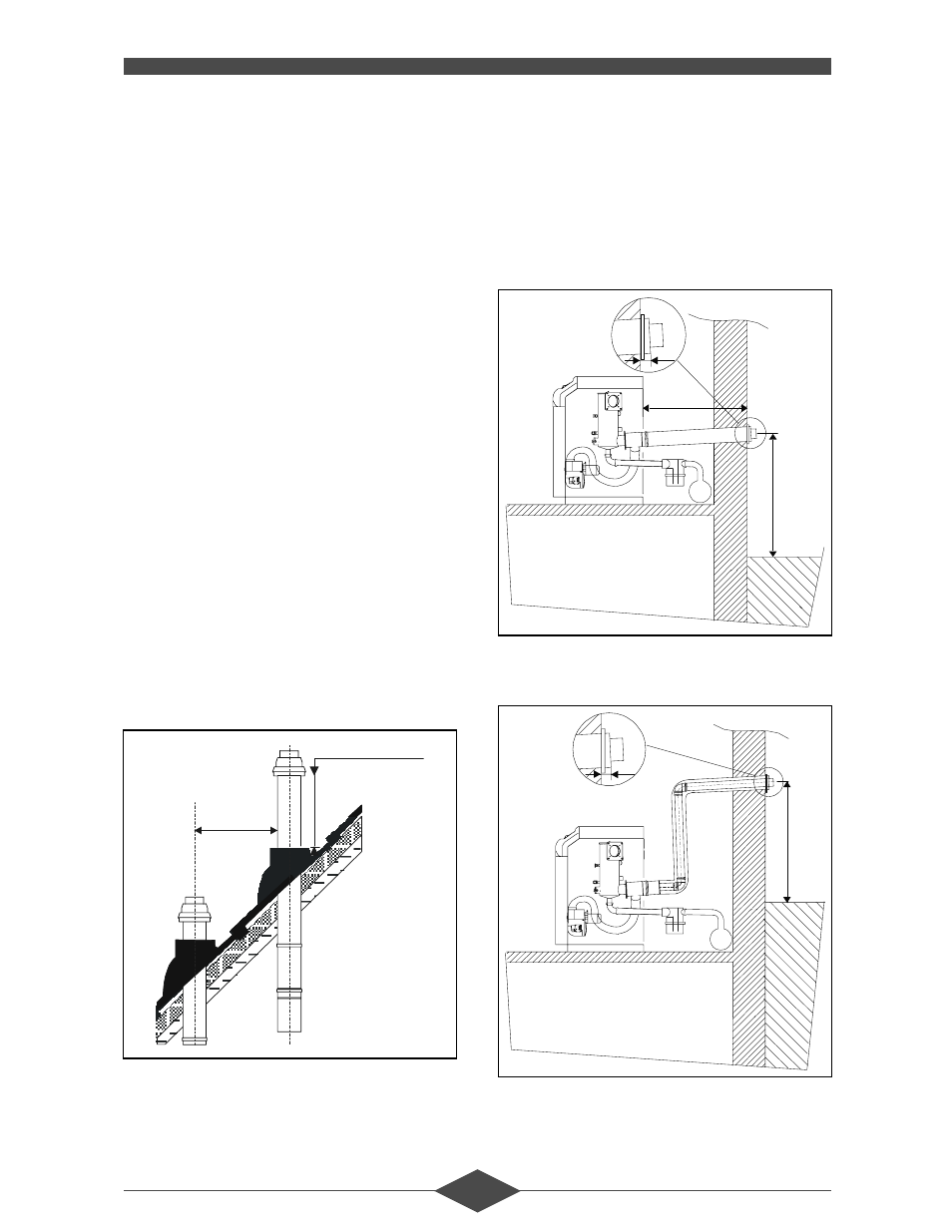
Typical installation examples appear in the illustra-
tion that follow.
6WUDLJKW %DODQFHG )OXH &RQILJXUDWLRQ
Option: Straight Horizontal Flue Kit
$QJOHG %DODQFHG )OXH &RQILJXUDWLRQ
Option: Angled Horizontal Flue Kit
40 cm
mini
30 cm
mini
16 In.
- 12 In.
1
,80 m
5.
9 f
t.
1 in
2.8 ft
1,
80
m
5.
9 f
t.
1 in