Assembly – MTD 240 Series User Manual
Page 6
6
3
Assembly
Stand behind the tiller
as if you were going to
operate it. Your right hand
corresponds to the right
side of the tiller; your left
hand corresponds to the
left side of the tiller.
IMPORTANT: This unit is
shipped without gasoline
or oil in the engine. Fill
up gasoline and oil as
instructed in the accom-
panying engine manual
BEFORE operating your
machine.
This operator’s manual
may cover various models
of tillers. The units il-
lustrated may vary slightly
from your unit.
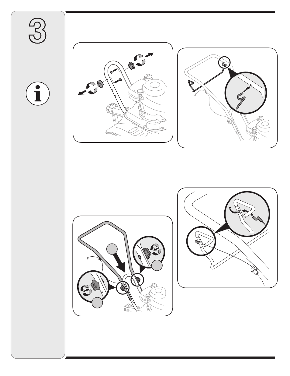
Figure 3-1: Remove hardware from lower handle.
Assembly
1. Remove the star handle knobs and carriage
bolts from the lower handle, Figure 3-1.
2. Position the upper handle onto the lower
handle, Step A Figure 3-2. Align the holes
on lower handle with the holes on the upper
handle (choose the upper or lower holes
depending on the desired handle height).
3. Insert carriage bolts through the holes and se-
cure with star knobs, Step B Figure 3-2. Make
certain carriage bolts are seated securely into
one of the two positions provided.
Figure 3-2: Attach and secure upper handle.
4. Insert left end of tine clutch control into the
hole on the left side of the upper handle,
Figure 3-3.
5. Insert the Z-fitting on the clutch cable into
the hole on the tine clutch control. Hook the
“Z” end into the opening from the inside to
the outside as shown in Figure 3-4.
Figure 3-3: Install left side of the tine clutch control.
Figure 3-4: Hook cable into tine clutch control.
A
B
B