Led indicators, Reset-type buttons, Led indicators -13 – Moxa Technologies UC-7400 User Manual
Page 16: Reset-type buttons -13
UC-7400 Hardware User’s Manual
Introduction
1-13
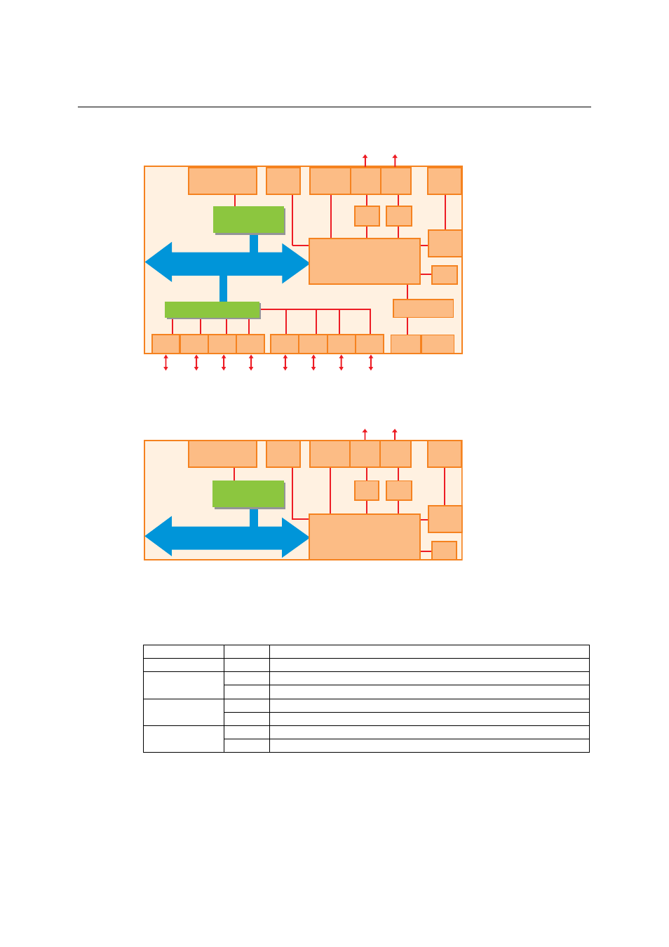
The following block diagram shows the layout of UC-7408’s internal components.
PCMCIA &
CompactFlash
Console
PHY
PHY
PCI Bus
RTC
Decoder
1
2
3
4
5
6
7
8
Moxa UART ASIC
USB
Client
PCI to cardbus
Bridge
Xscale IXP-422 266 MHz
32 MB Flash
128 MB SDRAM
RS-232
Power
Power
circuit
RS-232/422/485
Ethernet
LAN2 LAN1
D/I x 8 D/O x 8
The following block diagram shows the layout of UC-7402’s internal components.
PCMCIA &
CompactFlash
Console
PHY
PHY
PCI Bus
RTC
USB
Client
PCI to cardbus
Bridge
Xscale IXP-422 266 MHz
32 MB Flash
128 MB SDRAM
RS-232
Power
Power
circuit
Ethernet
LAN2 LAN1
LED Indicators
UC-7420/7410 /7408 have 12 LED indicators on the top panel. UC-7402 has only 4 LED
indicators (no serial port indicator) on the top panel. Refer to the following table for information
about each LED.
LED Name
Color
Meaning
Ready
Green
Power is ON, and system is ready (after booting up)
Yellow 10 Mbps Ethernet connection
LAN1, LAN2
Green
100 Mbps Ethernet connection
Yellow Console port is receiving RX data from the serial device.
Console
Green
Console port is transmitting TX data to the serial device.
Yellow Serial port is receiving RX data from the serial device.
P1, P2, P3, P4,
P5, P6, P7, P8
Green
Serial port is transmitting TX data to the serial device.
Reset-type Buttons
UC-7400 has two reset-type buttons. The button labeled Reset has the same effect as switching off
the power and then switching the power back on. The button labeled Reset to default returns
UC-7400 to the factory default parameter configuration.