Appendix c, Is8000 series pinout connection, Is8000 series pinout connections – Metrologic Instruments IS8000 User Manual
Page 31
27
A
PPENDIX
C
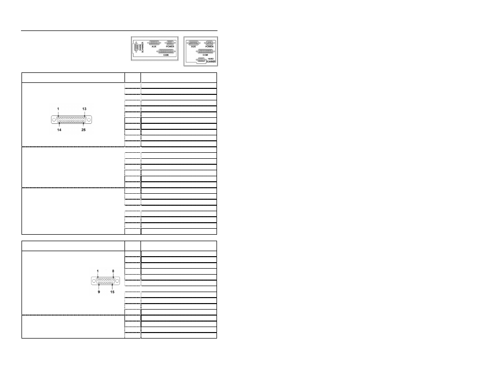
IS8000 Series Pinout Connections
D
ESCRIPTION
P
IN
S
IGNAL
1
Ground
2
RS-232 Receive Input
3
RS-232 Transmit Output
4
CTS Input
5
RTS Output
6
Reserved
7
Ground
8
Reserved
9
RS-422 Receive – (B-)
10
RS-422 Receive + (A+)
Connector Type on Scanner
DB25P (D-Type 25 Pin Male)
11
RS-422 Send + (Y+)
12
RS-422 Send – (Z-)
13
Ground
14
Ground
15
Light Pen Source
16
Light Pen Data
17
Reserved
Function:
Communication Pinouts for
RS-232/RS-422 and Light Pen Emulation.
18
Reserved
19
Open
20
DTR Input
21
Reserved
22
Reserved
23
Reserved
24
Reserved
25
Ground
RS-232 Cable Note: Cables for RS-232
should leave the RS-422 pins unterminated
at the scanner.
RS-422 Cable Note: Cables for RS-422
should leave the RS-422 should leave the
RS-232 transmit and receive pins
unterminated at the scanner.
D
ESCRIPTION
P
IN
S
IGNAL
1
RS-232 Receive Data (Input)
2
Clear to Send (Output)
3
Reserved
4
Reserved
5
Triac +
6
Sensor +
7
Sensor Alarm +
8
Reserved
9
RS-232 Transmit Data (Output)
10
Request to Send (Input)
Connector Type on Scanner:
DA15P (D-Type 15-Pin Male)
11
Signal Ground
12
Reserved
13
Triac -
14
Sensor -
Function:
Auxiliary RS-234 industrial Interface Port
15
Sensor Alarm -
IS8400/IS8500/IS8800
IS8300