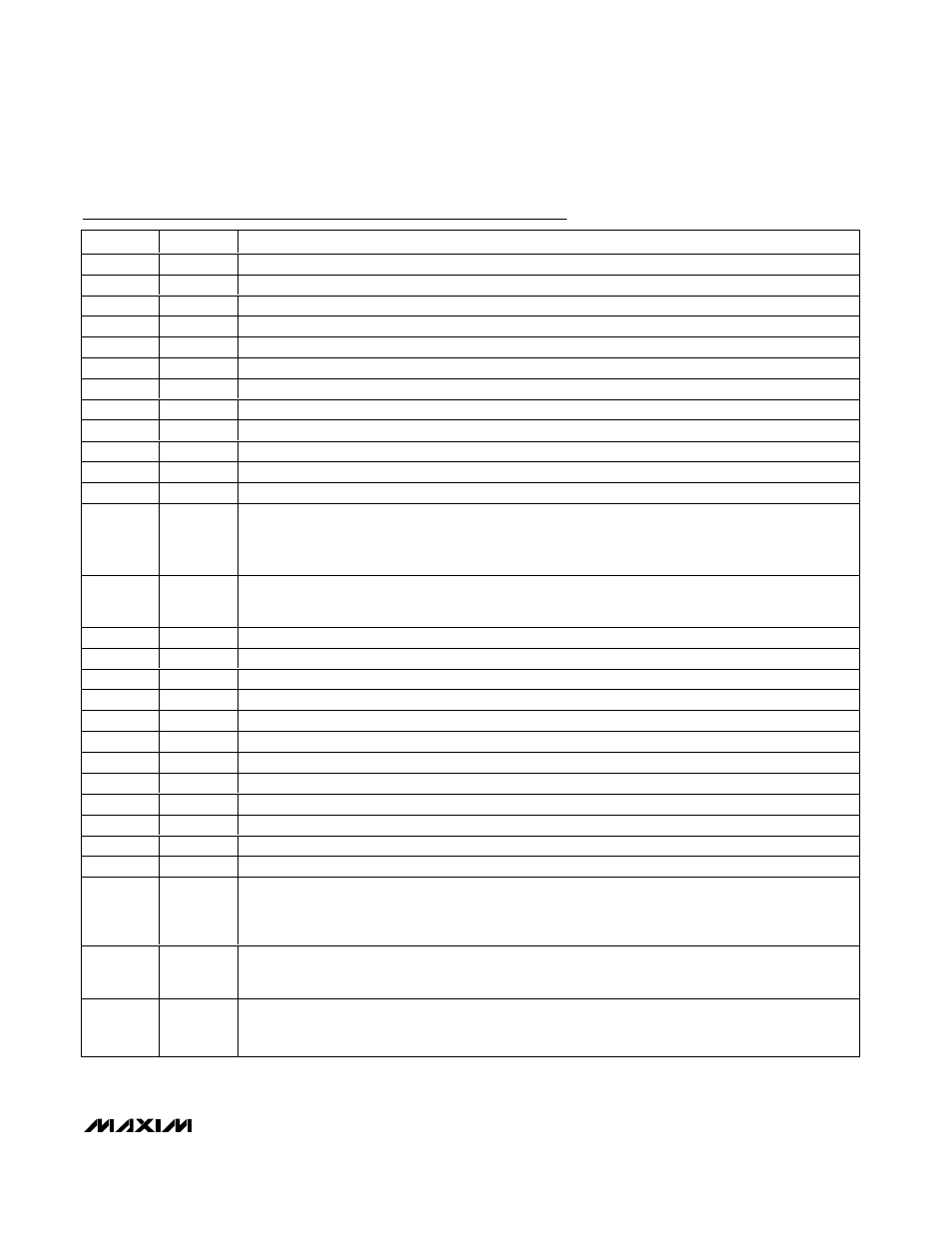
Pin description (continued) – Maxim Integrated MAX12527 User Manual
Page 13
MAX12527
Dual, 65Msps, 12-Bit, IF/Baseband ADC
______________________________________________________________________________________
13
PIN
NAME
FUNCTION
30
D0B
Channel B CMOS Digital Output, Bit 0 (LSB)
31
D1B
Channel B CMOS Digital Output, Bit 1
32
D2B
Channel B CMOS Digital Output, Bit 2
33
D3B
Channel B CMOS Digital Output, Bit 3
34
D4B
Channel B CMOS Digital Output, Bit 4
35
D5B
Channel B CMOS Digital Output, Bit 5
36
D6B
Channel B CMOS Digital Output, Bit 6
37
D7B
Channel B CMOS Digital Output, Bit 7
38
D8B
Channel B CMOS Digital Output, Bit 8
39
D9B
Channel B CMOS Digital Output, Bit 9
40
D10B
Channel B CMOS Digital Output, Bit 10
41
D11B
Channel B CMOS Digital Output, Bit 11 (MSB)
42
DORB
Channel B Data Out-of-Range Indicator. The DORB digital output indicates when the channel B analog
input voltage is out of range.
DORB = 1: Digital outputs exceed full-scale range.
DORB = 0: Digital outputs are within full-scale range.
44
DAV
Data-Valid Digital Output. The rising edge of DAV indicates that data is present on the digital outputs.
The MAX12527 evaluation kit (MAX12557 EV kit) utilizes DAV to latch data into any external back-end
digital logic.
47
D0A
Channel A CMOS Digital Output, Bit 0 (LSB)
48
D1A
Channel A CMOS Digital Output, Bit 1
49
D2A
Channel A CMOS Digital Output, Bit 2
50
D3A
Channel A CMOS Digital Output, Bit 3
51
D4A
Channel A CMOS Digital Output, Bit 4
52
D5A
Channel A CMOS Digital Output, Bit 5
53
D6A
Channel A CMOS Digital Output, Bit 6
54
D7A
Channel A CMOS Digital Output, Bit 7
55
D8A
Channel A CMOS Digital Output, Bit 8
56
D9A
Channel A CMOS Digital Output, Bit 9
57
D10A
Channel A CMOS Digital Output, Bit 10
58
D11A
Channel A CMOS Digital Output, Bit 11 (MSB)
59
DORA
Channel A Data Out-of-Range Indicator. The DORA digital output indicates when the channel A analog
input voltage is out of range.
DORA = 1: Digital outputs exceed full-scale range.
DORA = 0: Digital outputs are within full-scale range.
64
G/T
Output Format Select Digital Input.
G/T = GND: Two’s-complement output format selected.
G/T = OV
DD
: Gray-code output format selected.
65
PD
Power-Down Digital Input.
PD = GND: ADCs are fully operational.
PD = OV
DD
: ADCs are powered down.
Pin Description (continued)