Section 3 − introduction, 1. specifications, 2. remote 7 receptacle information – Miller Electric XMS 44 User Manual
Page 11: 3. 14-pin plug information
OM-223 839 Page 7
SECTION 3 − INTRODUCTION
3-1. Specifications
Type of Input
Power
Welding Power
Source Type
Wire Feed
Speed Range
Wire Diameter Range
Welding
Circuit
Rating
Overall
Dimensions
Weight
24 Volts AC
Single-Phase
7 Amperes
50/60 Hertz
XMS 4000 Welding Power
Source
0.5 − 20 m/min
0.8 mm − 1.8 mm
Max Spool Weight:
15 kg
36 Volts,
400
Amperes,
30% Duty
Cycle
Length: 640 mm
Width: 225 mm
Height: 435 mm
23 kg
3-2. Remote 7 Receptacle Information
Pin
Pin Information
1
+10 volts DC supply voltage to remote control
2
GND Remote control circuit common
3
IREF 0 to 10 current control signal
4
VREF 0 to 10 voltage control signal
5
UP 0V/10V digital signal
6
DOWN 0V/10V digital signal
Remote 7
7
TYPE 0V/10V digital signal
Note: This remote receptacle cannot be used with a standard Miller remote control. A customer supplied remote control is required to use the
remote receptacle.
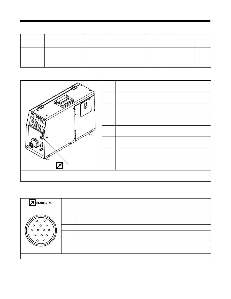
3-3. 14-Pin Plug Information
Pin*
Pin Information
A
24 volts AC with respect to socket G. Protected by circuit breaker CB1.
B
GND of communciation signals.
A
J K
A
J K
C
Serial communciation signal −485.
A
J K
A
J
B
K
I
B
I
D
Serial communication signal +485.
C
L
N
H
D
M
H
D
M
G
E
Start motor signal to XMS 44.
D
M
D
M
G
E
F
E
F
F
Trigger switch signal to XMS 4000.
E
F
E
F
G
Circuit common for 24 volts AC circuit.
H
Wire feeder speed signal to XMS 44.
*The remaining pins are not used.